Mounting bracket for slide assembly

Active Publication Date: 2015-03-12
KING SLIDE WORKS CO LTD +1
View PDF32 Cites 53 Cited by
  • Summary
  • Abstract
  • Description
  • Claims
  • Application Information

AI Technical Summary

Benefits of technology

[0017]The primary object of the present invention is to provide a mounting bracket for a slide assembly. The slide assembly is

Problems solved by technology

However, the abutment member utilized to abut against the rack and disclosed by Allen et al. is a metal resilient pl

Method used


Image

  • Mounting bracket for slide assembly
  • Mounting bracket for slide assembly
  • Mounting bracket for slide assembly

Examples


second embodiment

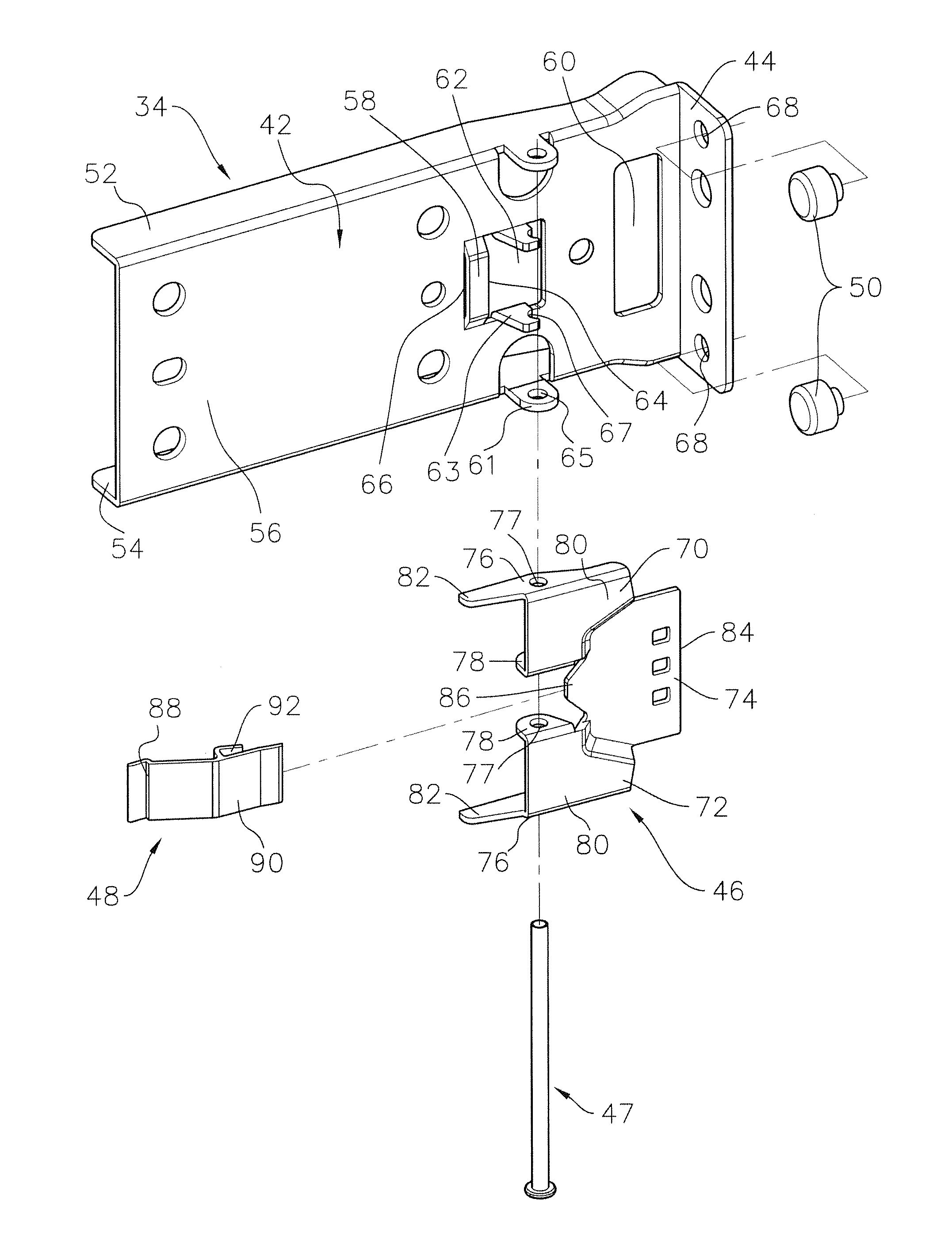
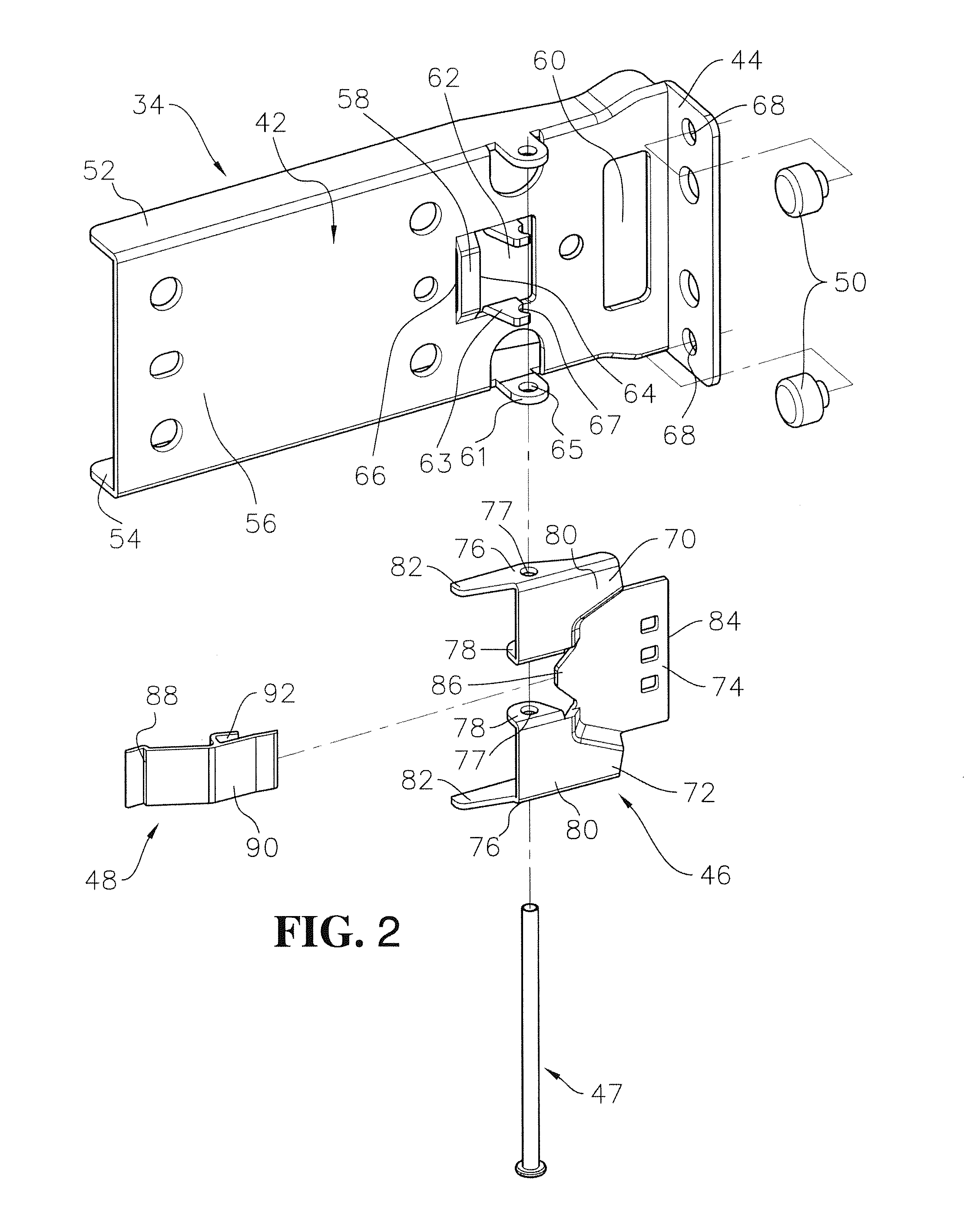
[0034]FIG. 7 shows the present invention, wherein the stop 200 of the first mounting bracket 34 can only comprise the first portion 202 and the middle portion 204. The middle portion 204 has a side plate 206 to fix the resilient member 48.

third embodiment

[0035]FIG. 8 shows the present invention, wherein the resilient member 300 has two bent portions 302 at two ends thereof respectively. The two bent portions 302 respectively contact the contact member 58 of the first mounting bracket 34 and the second end portion 86 of the stop 46.

[0036]While we have shown and described the embodiment in accordance with the present invention, it should be clear to those skilled in the art that further embodiments may be made without departing from the scope of the present invention.


PUM


Abstract

A mounting bracket for a slide assembly includes a side wall, an end wall, at least one installation member, a stop, and a resilient member. The end wall is substantially perpendicular to the side wall. The at least one installation member is connected to the end wall. The stop is pivotably connected to the side wall and includes a first portion and a middle portion which is connected to the first portion. The middle portion has a first end portion. The resilient member provides a force to the stop to position the first end portion of the stop to be located corresponding to the end wall.

Description

FIELD OF THE INVENTION[0001]The present invention relates to a mounting bracket, and more particularly, to a mounting bracket for a slide assembly.BACKGROUND OF THE INVENTION[0002]U.S. Pat. No. 7,281,694 B2 to Allen et al. discloses a mounting bracket having a side plate, an end plate, a base member, a pair of pins, an abutment member and an action mechanism, wherein the abutment member has a free end. The pins are installed to the end plate of the mounting bracket, and the base member is connected to the side plate. The abutment member is fixed to the base member, and the action mechanism extends through the base member and contacts the abutment member. When the pins are installed to the holes of a post of a rack, the abutment member is deformed to allow the post of the rack to pass therethrough and abuts against the post of the rack, so as to form an enclosed room with the pins.[0003]However, the abutment member utilized to abut against the rack and disclosed by Allen et al. is a ...

Claims


Application Information

Patent Timeline
IPC IPC(8): A47B96/06A47B96/14A47B46/00
CPCA47B96/06A47B96/145A47B46/00H05K7/1489A47B88/43A47B2088/4235A47B47/0058A47B96/07A47B96/1441H05K7/1498A47B96/068A47B96/1408A47B96/1458A47B96/067
Inventor CHEN, KEN-CHINGYANG, SHUN-HOTSENG, I-MINGHO, CHUN-YIWANG, CHUN-CHIANG
Owner KING SLIDE WORKS CO LTD
Why Eureka
Try Eureka