Multi-beam antenna with modular luneburg lens and method of lens manufacture

a technology of modular luneburg and antenna, applied in the field of radio communication, can solve the problems of increasing costs and space requirements, dividing a coverage area into smaller sectors, and drawbacks, and achieve the effects of narrowing the beamwidth of the antenna, increasing the associated gain, and reducing the cost of installation

Active Publication Date: 2015-03-12
COMMSCOPE TECH LLC
View PDF11 Cites 72 Cited by
  • Summary
  • Abstract
  • Description
  • Claims
  • Application Information

AI Technical Summary

Benefits of technology

[0006]The present inventions achieve technical advantages by using a variation of a Luneburg lens to narrow an antenna's beamwidth and increase its associated gain. This enables the use of less expensive and less cumbersome antennas to cover smaller areas while simultaneously increasing overall system capacity and decreasing interference across sectors. In some embodiments, the lens includes a modular design that allows for the lens size to be changed easily and efficiently.

Problems solved by technology

However, dividing a coverage area into smaller sectors has drawbacks because antennas covering narrow sectors generally have more radiating elements that are spaced wider than antennas covering wider sectors.
Thus, costs and space requirements increase as a cell is divided into a greater number of sectors.

Method used


Image

  • Multi-beam antenna with modular luneburg lens and method of lens manufacture
  • Multi-beam antenna with modular luneburg lens and method of lens manufacture
  • Multi-beam antenna with modular luneburg lens and method of lens manufacture

Examples


Embodiment Construction

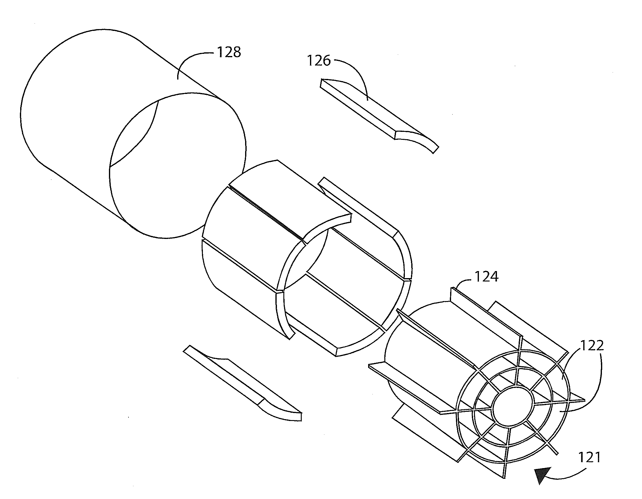
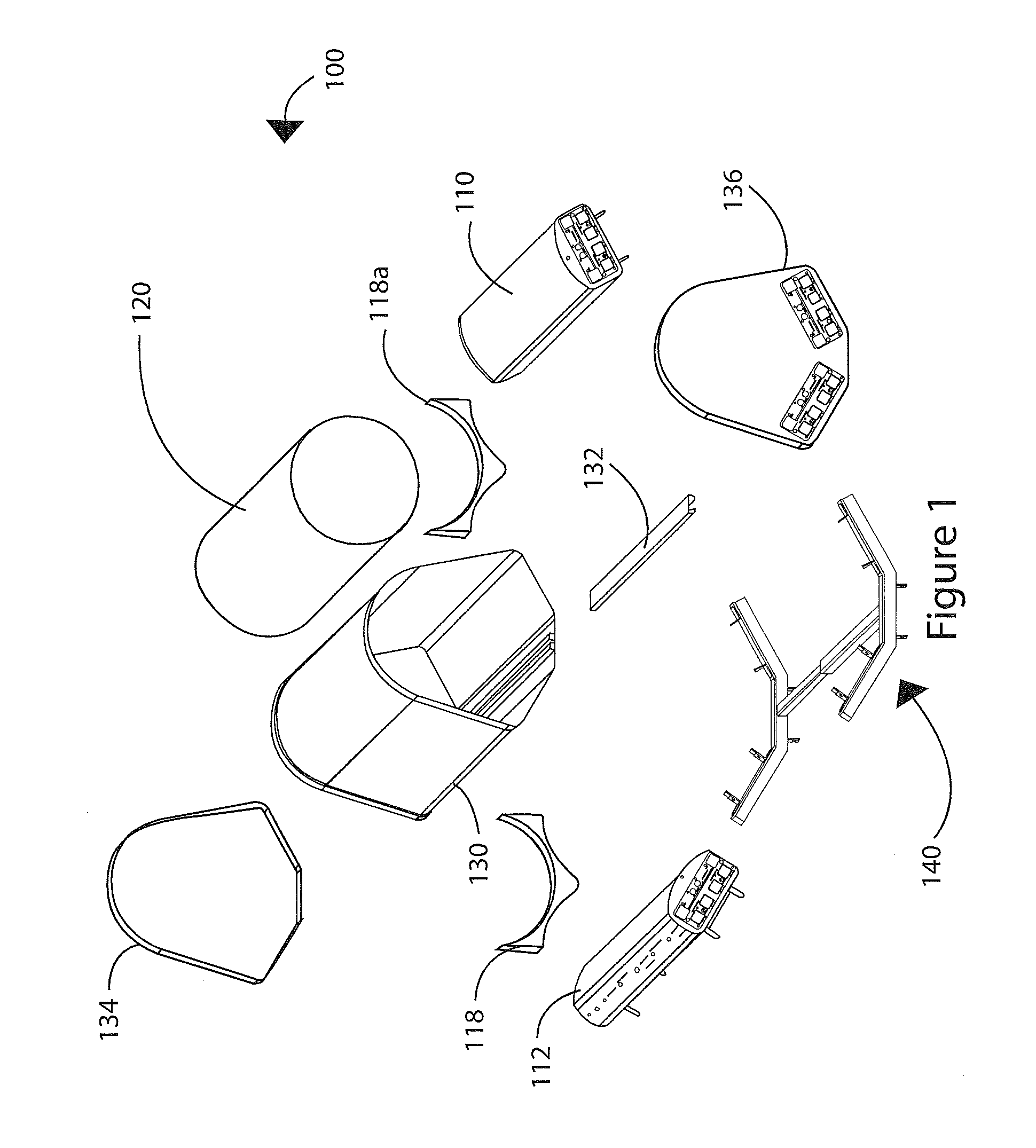
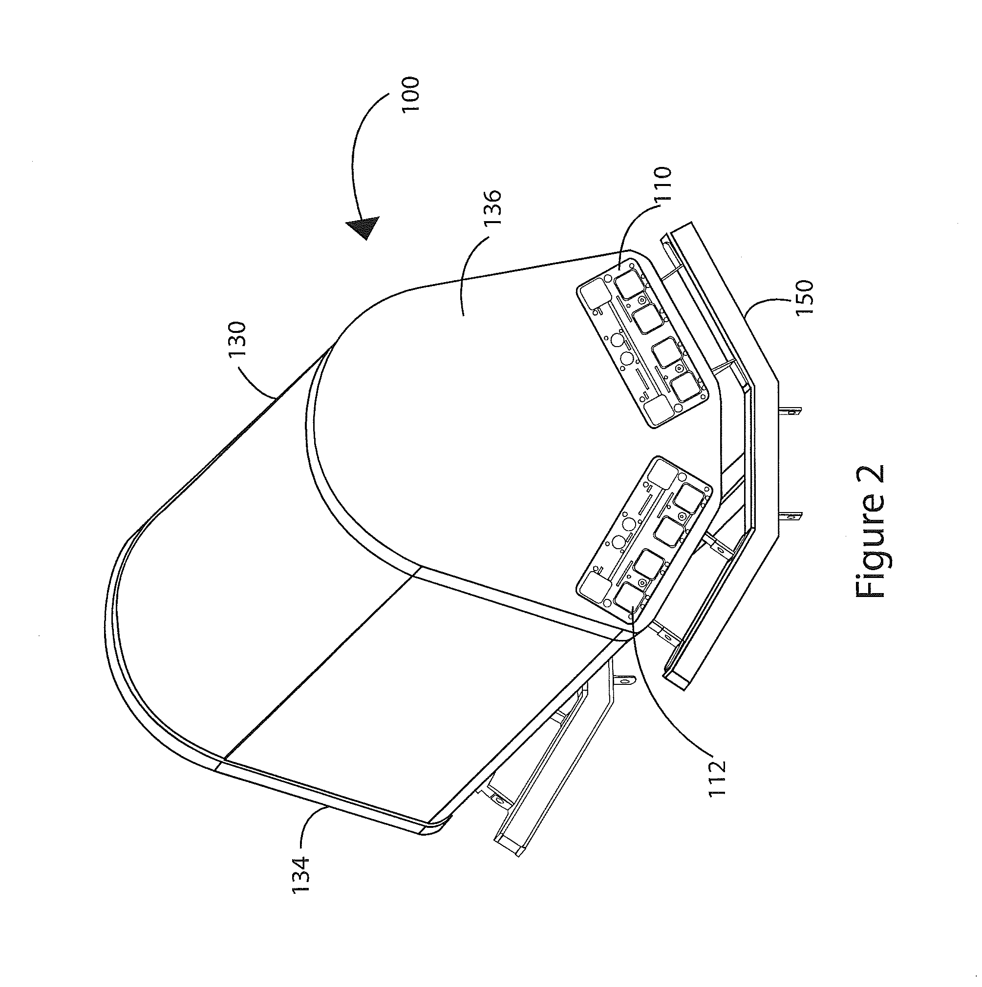
[0018]Referring to the drawings, and initially to FIG. 1, a multiple beam base station antenna system 100 is illustrated in an exploded view. The multiple beam antenna system 100 includes a first wireless access antenna 110, a second wireless access antenna 112, a lens 120, top and bottom lens supports 122a and 122b, a shroud 130, a shroud locking device 132, a top end cap 134, a bottom end cap 136, and a telescopic mounting structure 150. An assembled view of the multiple beam antenna is illustrated in FIG. 2.

[0019]In some embodiments, the wireless access antennas 110 and 112 may be, for example, any 65° HPBW multi-band antenna. Such multi-band antennas are referred to herein as “single beam” antennas because, while each band may have its own separately controllable beam, there is only a single beam per band. Alternatively, or additionally, single band antennas or antennas of other half power beam widths may be used. In this respect, one of the advantages of the systems described h...


PUM


Abstract

A multiple beam antenna system is described. The system may include a mounting structure, a first wireless access antenna, a second wireless access antenna, and a radio frequency lens. The first and second wireless access antennas may be mounted to the mounting structure. Columns of radiating elements of the first and second wireless access antennas may be aligned with the radio frequency lens. The radio frequency lens may be modular in a longitudinal or radial direction, or in both directions. The radio frequency lens may include a plurality of compartments arranged to form a first cylinder made up of concentric, coaxial cylinders and a plurality of dielectric materials in at least some of the plurality of compartments.

Description

CROSS REFERENCE TO RELATED APPLICATIONS[0001]This application claims priority to U.S. Provisional Application Ser. No. 61 / 875,491 filed Sep. 9, 2013, which is hereby incorporated by reference in its entirety.BACKGROUND[0002]The present inventions generally relate to radio communications and, more particularly, to multi-beam antennas utilized in cellular communication systems.[0003]Cellular communication systems derive their name from the fact that areas of communication coverage are mapped into cells. Each such cell is provided with one or more antennas configured to provide two-way radio / RF communication with mobile subscribers geographically positioned within that given cell. One or more antennas may serve the cell, where multiple antennas commonly utilized are each configured to serve a sector of the cell. Typically, these plurality of sector antennas are configured on a tower, with the radiation beam(s) being generated by each antenna directed outwardly to serve the respective c...

Claims


Application Information

Patent Timeline
Patent Type & Authority Applications(United States)
IPC IPC(8): H01Q19/06
CPCH01Q19/06H01Q1/246H01Q1/42H01Q15/08H01Q21/062H01Q21/24H01Q21/08H01Q19/062H01Q21/06H01Q1/24
Inventor BRADLEY, EDDIE RAYTIMOFEEV, IGOR E.BONCZYK, MICHAEL F.BURNETT, WILLAIM H.
Owner COMMSCOPE TECH LLC
Why Eureka
Try Eureka