Optical touch panel and touchscreen

Inactive Publication Date: 2015-03-12
WINTEK CORP
View PDF9 Cites 27 Cited by
  • Summary
  • Abstract
  • Description
  • Claims
  • Application Information

AI Technical Summary

Benefits of technology

[0050]Based on above, since the light beam provided by the light-emitting element can travel inside the light guide plate and be scattered to the optical sensing element, the optical touch panel of the invention can be applied in touch sensing. In addition, by disposing the optical sensing element under the bottom surface of the light guide plate, the optical

Problems solved by technology

In case the touch panel is applied in medium and large displays, both resistive touch panels and capacitive touch panels require to use a sensor electrode made of a transparent conductive film approximately matching a size of the panel, thus a transmission impedance of the sensor electrode is significantly increased to further increase difficulty in sensing.
Accordingly, process yield may be poor and cost may be higher, thus research and development in optical touch panel technology is now an important development direction in the field.
However, such a determination principle requires the sensors and light sources (emitters) being dispos

Method used


Image

  • Optical touch panel and touchscreen
  • Optical touch panel and touchscreen
  • Optical touch panel and touchscreen

Examples


Example

[0072]To make the above features and advantages of the disclosure more comprehensible, several embodiments accompanied with drawings are described in detail as follows. It should be noted that, numerical ranges provided in the following embodiments are used only for illustration, and are not intended to limit the scope of the present invention.

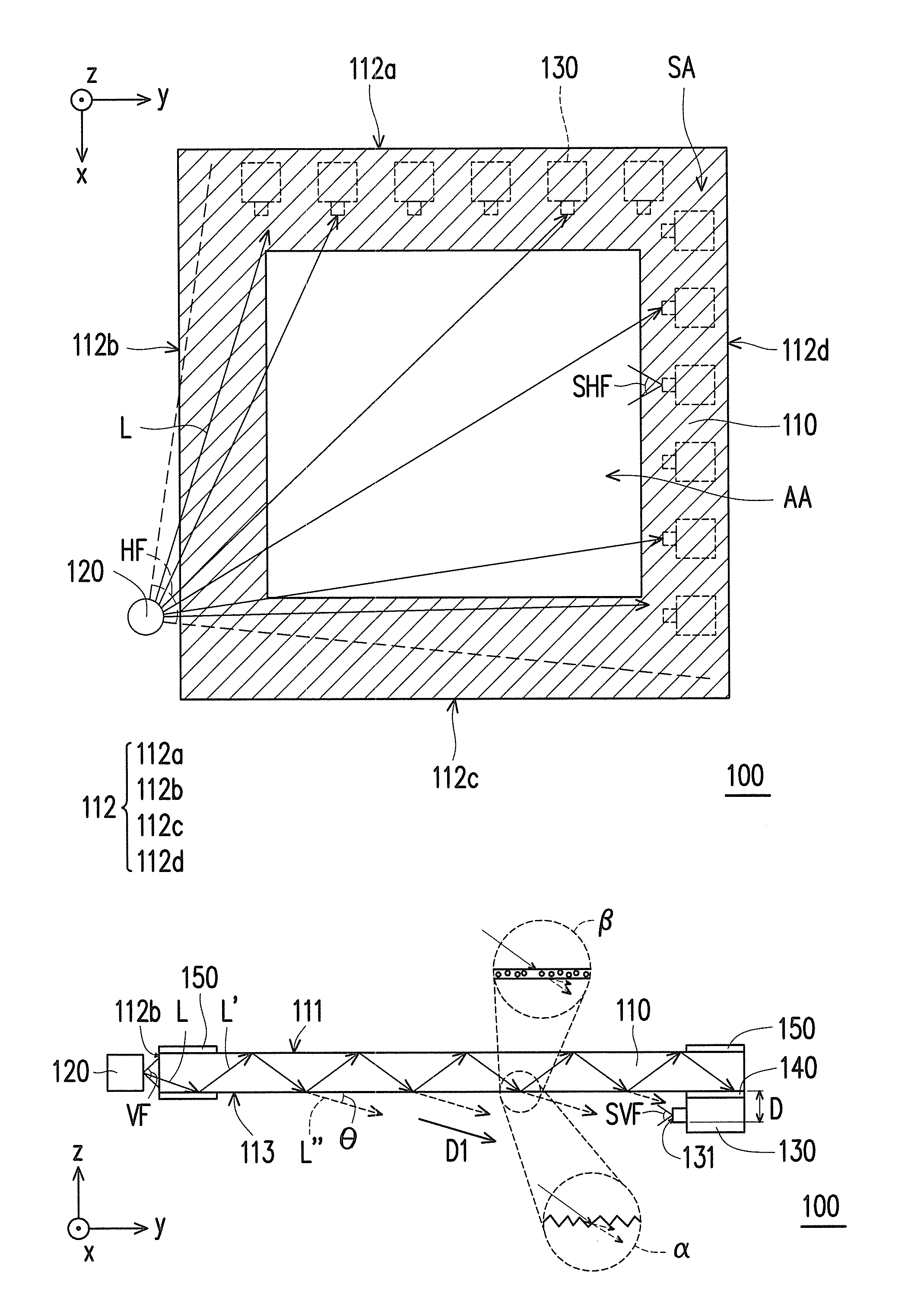
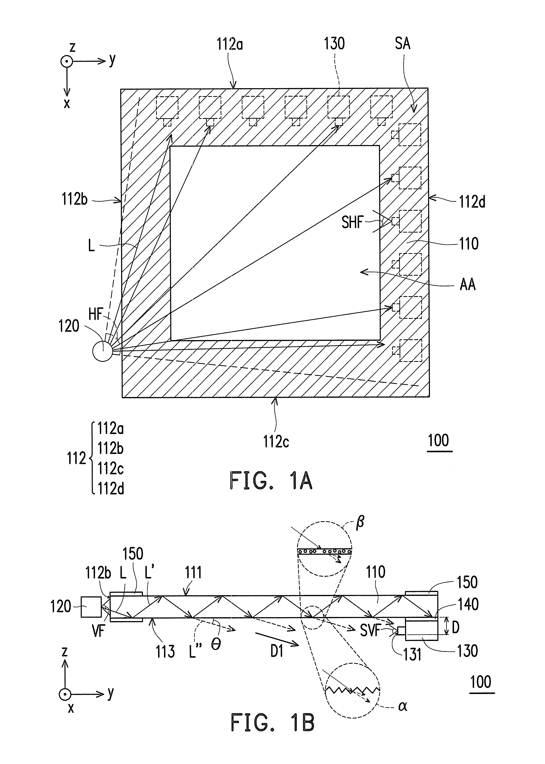
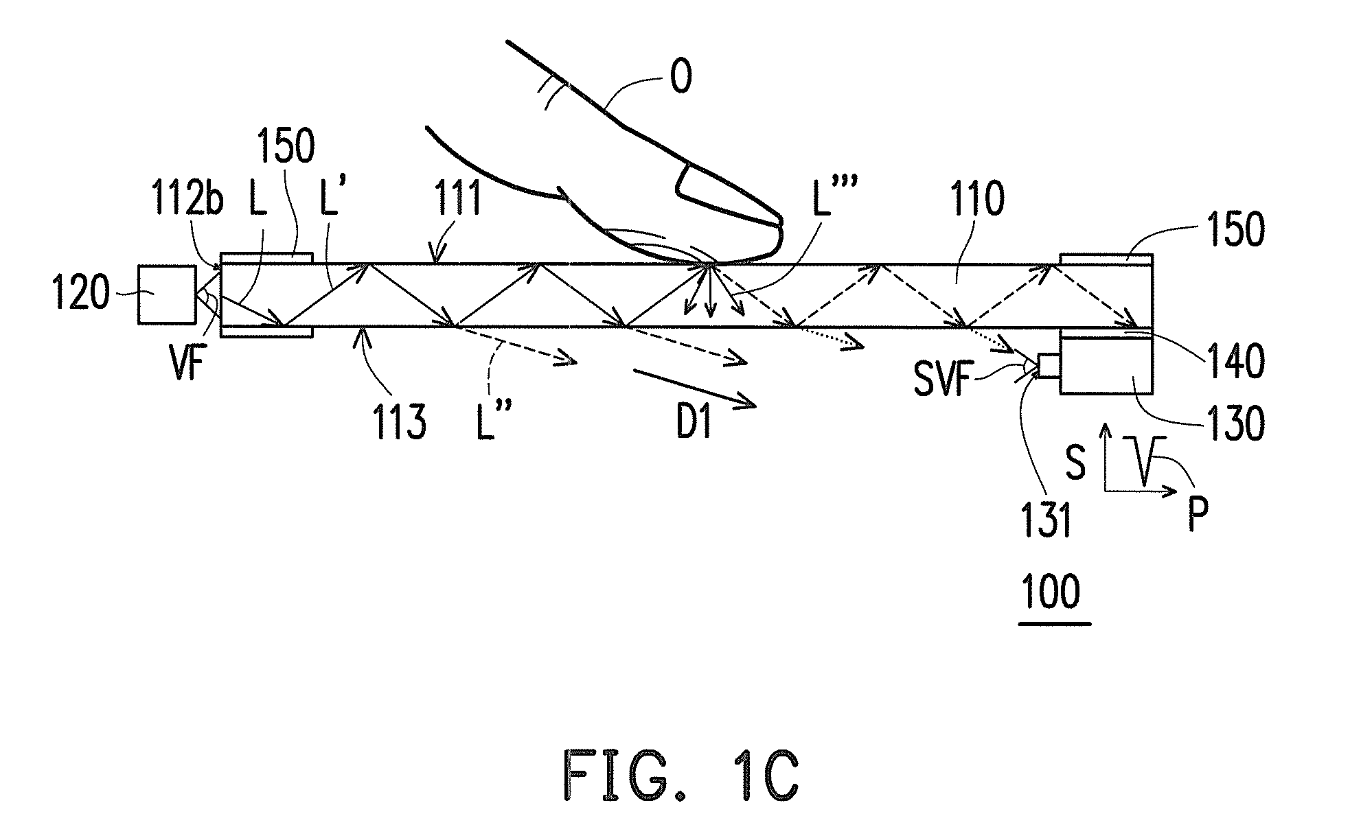
[0073]FIG. 1A is a schematic top view of an optical touch panel according to an embodiment of the invention. FIG. 1B is a schematic side view of the optical touch panel depicted in FIG. 1A. FIG. 1C is a schematic side view of the optical touch panel depicted in FIG. 1A being touched by an object. Referring to FIG. 1A to FIG. 1C, in the present embodiment, an optical touch panel 100 includes a light guide plate 110, at least one light-emitting element 120 and a plurality of optical sensing elements 130. For instance, a material of the light guide plate 110 may be a glass or a plastic material, or the light guide plate 110 may be a composite pla...


PUM


Abstract

An optical touch panel including a light guide plate, at least one light-emitting element and a plurality of optical sensing elements and a touchscreen using the same are provided. The light guide plate has a plurality of lateral surfaces, a top surface, a bottom surface and a light extraction structure. The light-emitting element provides a light beam entering the light guide plate. The optical sensing elements are disposed under the bottom surface of the light guide plate. Each of the optical sensing elements has a sensing surface not parallel to the bottom surface of the light guide plate. The optical sensing elements are disposed at an illuminated region of the light beam provided by the light-emitting element. By the light extraction structure, a second portion of the light beam entered the light guide plate is scattered to the optical sensing elements from the bottom surface.

Description

CROSS-REFERENCE TO RELATED APPLICATION[0001]This application claims the priority benefit of Taiwan application serial no. 102132853, filed on Sep. 11, 2013. The entirety of the above-mentioned patent application is hereby incorporated by reference herein and made a part of this specification.BACKGROUND OF THE INVENTION[0002]1. Field of the Invention[0003]The invention relates to a touch panel and a touchscreen, and more particularly to an optical touch panel and a touchscreen using the same.[0004]2. Description of Related Art[0005]In recent years, with information and electronic technologies progressed at a tremendous pace, touchscreens have been widely applied and led to applications and developments of consumer electronics products, such as portable electronic devices including cell phone, notebook computer, personal digital assistant (PDA), global positioning system (GPS). The touchscreens have become one independent industry owing to advantages in easy communication for users to...

Claims


Application Information

Patent Timeline
IPC IPC(8): G06F3/042
CPCG06F3/0421G06F2203/04109
Inventor HSIEH, TSUNG-YENFANG, CHONG-YANGWANG, WEN-CHUN
Owner WINTEK CORP
Why Eureka
Try Eureka