System and moving modulated target with unmodulated position references for characterization of imaging sensors

Active Publication Date: 2015-03-12
RAYTHEON CO
View PDF1 Cites 10 Cited by
  • Summary
  • Abstract
  • Description
  • Claims
  • Application Information

AI Technical Summary

Benefits of technology

The patent describes a system for characterizing electro-optical imaging sensors using a moving target. The system creates a known target pattern with different emission intensities and measures the position of the target. The system then uses the target to create a high-resolution composite image by combining different images of the same objects taken at different positions. This composite image is then used to determine the shape of blur at different locations in the image. The system can also have different materials, like a surface coating or a micro-texture, that change the emission intensity of the target. Overall, the system creates a detailed understanding of how the imaging sensor responds to a moving target and can be used for blur calibration.

Problems solved by technology

One problem with imaging systems is the amount of image blur that is attributable to their optics and other components.
This is extraordinarily difficult as it may require measuring an unresolved (near point) source at a resolution that is far higher than the pixel resolution the imaging sensor.
In some cases, it may also be necessary to measure the change in the PSF across the field-of-view (FOV) of an imaging sensor, compounding the blur-calibration problem.
This blur-calibration problem is markedly more difficult in systems where the required precision or other conditions, such as operation in cryo-vacuum conditions, make it impractical to project precision collimated patterns that fill the sensor's entire FOV.
Conventional approaches used to blur-calibrate electro-optic sensors in a cryo-vacuum chamber are time-consuming, expensive and limited in accuracy.

Method used


Image

  • System and moving modulated target with unmodulated position references for characterization of imaging sensors
  • System and moving modulated target with unmodulated position references for characterization of imaging sensors
  • System and moving modulated target with unmodulated position references for characterization of imaging sensors

Examples


Embodiment Construction

[0024]The following description and the drawings sufficiently illustrate specific embodiments to enable those skilled in the art to practice them. Other embodiments may incorporate structural, logical, electrical, process, and other changes. Portions and features of some embodiments may be included in, or substituted for, those of other embodiments. Embodiments set forth in the claims encompass all available equivalents of those claims.

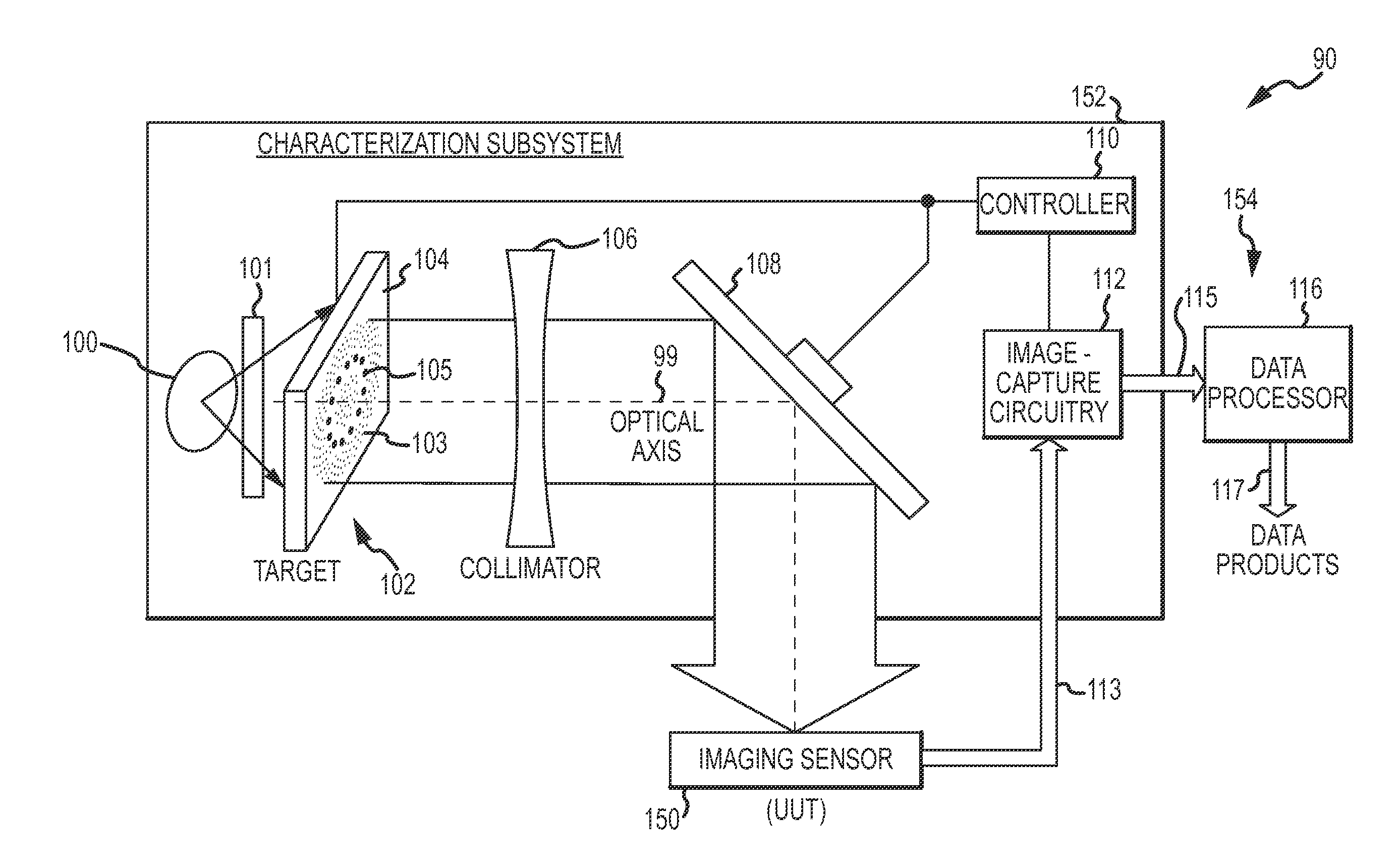
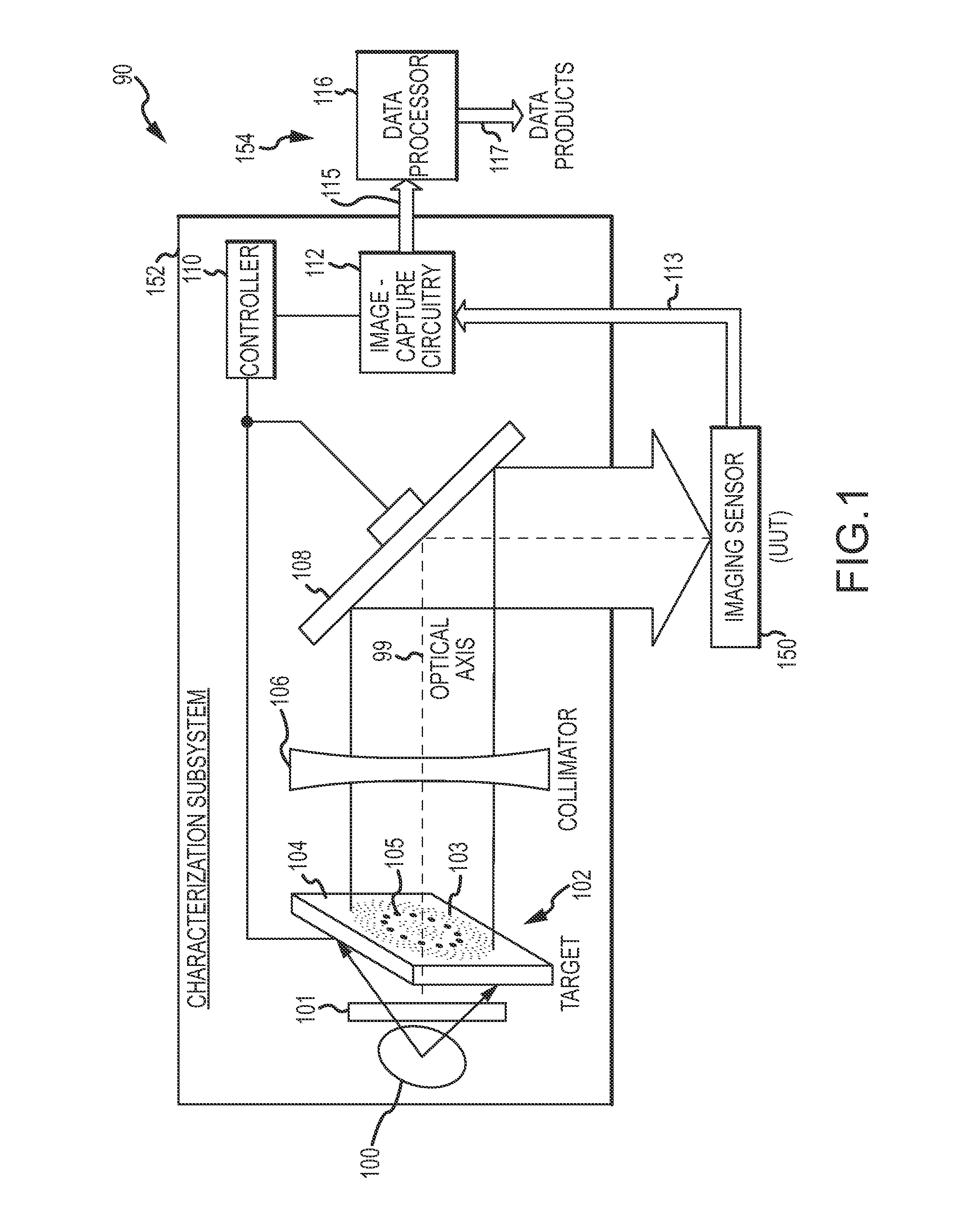
[0025]FIG. 1 illustrates a system for characterization of an imaging sensor in accordance with some embodiments. System 90 may be configured for performing optical measurement or calibration for an electro-optical sensor, such as imaging sensor 150. Imaging sensor 150 comprises both the sensor and the optics assembly that focuses collimated light onto the sensor. The system 90 may include a characterization subsystem 152 to capture image data from the imaging sensor 150 and a data processing subsystem 154 to process the image data output 115 from the ...


PUM


Abstract

Embodiments of a system for characterization of an imaging sensor using a moving modulated target with unmodulated position references is generally described herein. A target pattern comprises through-holes in a slide and resolved patches on the slide. The slide and patch have different emission intensities in the sensor’ detection band. A modulation is applied to only the emission intensities of the through-holes. The target pattern is moved across the field-of view (FOV) of the imaging sensor to present the target pattern across different frames at different positions. Frames of images of the moving target pattern as seen in the FOV of the imaging sensor are captured to generate modulated image data outputs. The unmodulated position references provided by the resolved patches are measured and used to align the modulated image data outputs, which are processed to generate data products representative of a response of the imaging sensor.

Description

RELATED APPLICATION[0001]This patent application is related to U.S. patent application entitled “BLUR-CALIBRATION SYSTEM FOR ELECTRO-OPTICAL SENSORS AND METHOD USING A MOVING MULTI-TARGET CONSTELLATION”, Ser. No. 13 / 214,683 filed Aug. 22, 2011, the entire contents of which is incorporated by reference.GOVERNMENT RIGHTS[0002]This invention was made with United States Government support under Contract Number HQ0276-10-C-0005 with the Missile Defense Agency. The United States Government has certain rights in this invention.TECHNICAL FIELD[0003]Some embodiments pertain to imaging systems. Some embodiments pertain to characterization of imaging sensors including electro-optical sensors. Some embodiments pertain to alignment of modulated images, particularly modulated composite images and / or modulated on and off images. Some embodiments pertain to measurement or calibration of imaging sensors. Some embodiments pertain to space-astronomy systems. Some embodiments pertain to kill vehicles a...

Claims


Application Information

Patent Timeline
IPC IPC(8): H04N17/00
CPCH04N17/002
Inventor WILLIAMS, DARIN S.
Owner RAYTHEON CO
Why Eureka
Try Eureka