Actuator unit

a technology of actuator unit and actuator body, which is applied in the direction of dynamo-electric components, dynamo-electric machines, instruments, etc., can solve the problems of color permeation or dimming, image quality degradation, etc., and achieve the effect of simple assembly and mutual separation

Inactive Publication Date: 2015-03-12
HUIZHOU DAYAWAY EVER BRIGHT ELECTRONICS IND CO LTD +2
View PDF2 Cites 7 Cited by
  • Summary
  • Abstract
  • Description
  • Claims
  • Application Information

AI Technical Summary

Benefits of technology

[0043]In this way, if the spoke part is divided into the first spoke parts of which one end is connected with the inner side retaining part and the second spoke parts of which one end is connected with the outer side retaining part, the other ends of the first spoke parts and the second spoke parts are mutually connected together on the outer side of the outer side retaining part, the inner side retaining part and the outer side retaining part can be mutually separated easily, and the assembling working procedure of the actuator unit becomes simple.

Problems solved by technology

The image focused on the image sensor is twisted for the inclined lens 31, which leads to color permeation or dimming, and the problem of image quality degradation such as image stress.

Method used


Image

  • Actuator unit
  • Actuator unit
  • Actuator unit

Examples


Embodiment Construction

[0063]The invention will now be described in detail through several embodiments with reference to the accompanying drawings.

[0064]The present invention is described through the embodiments as follows, the following embodiments do not limit claims in the present invention, and the combination of all features described in the embodiments does not necessary for solutions of the present invention.

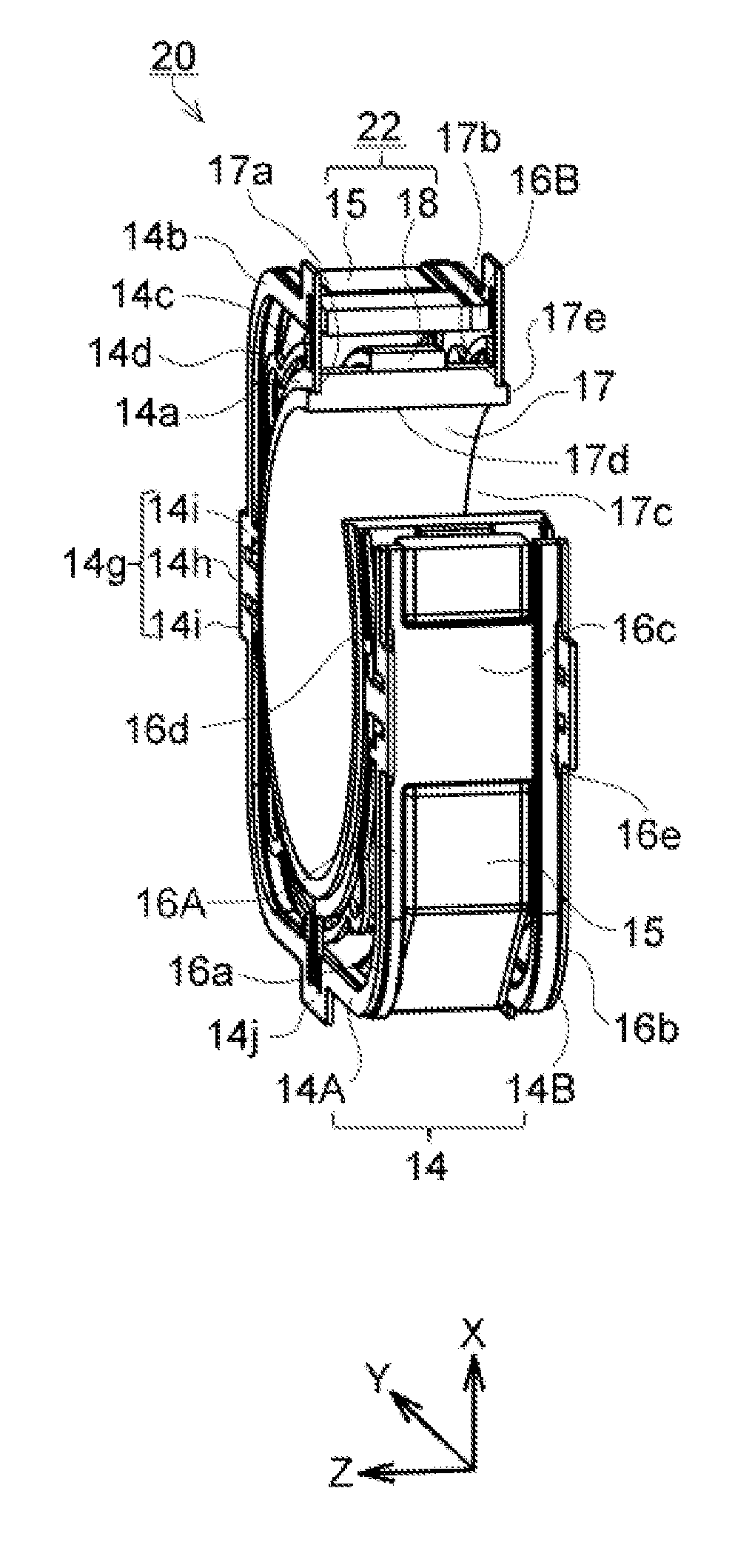
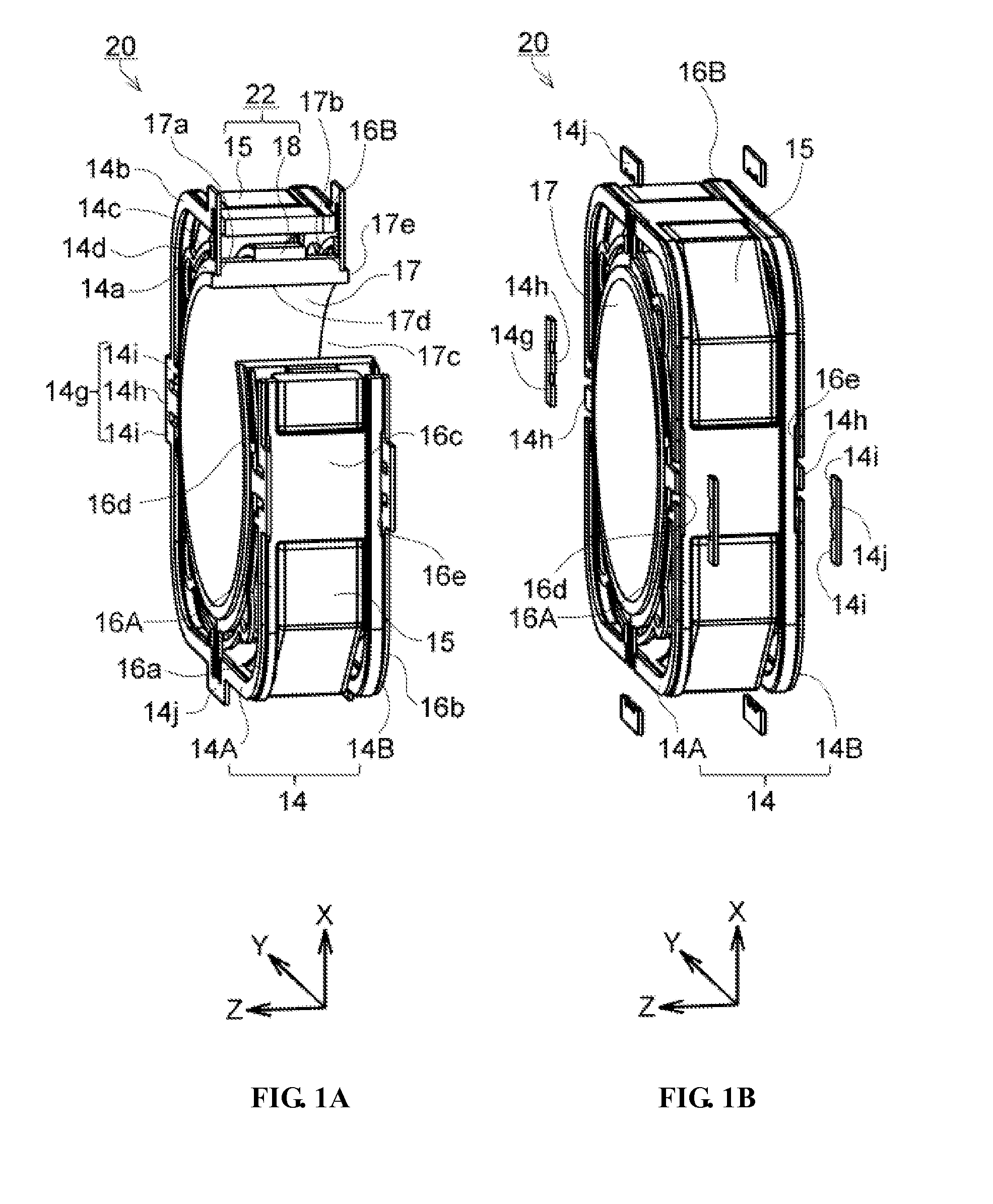
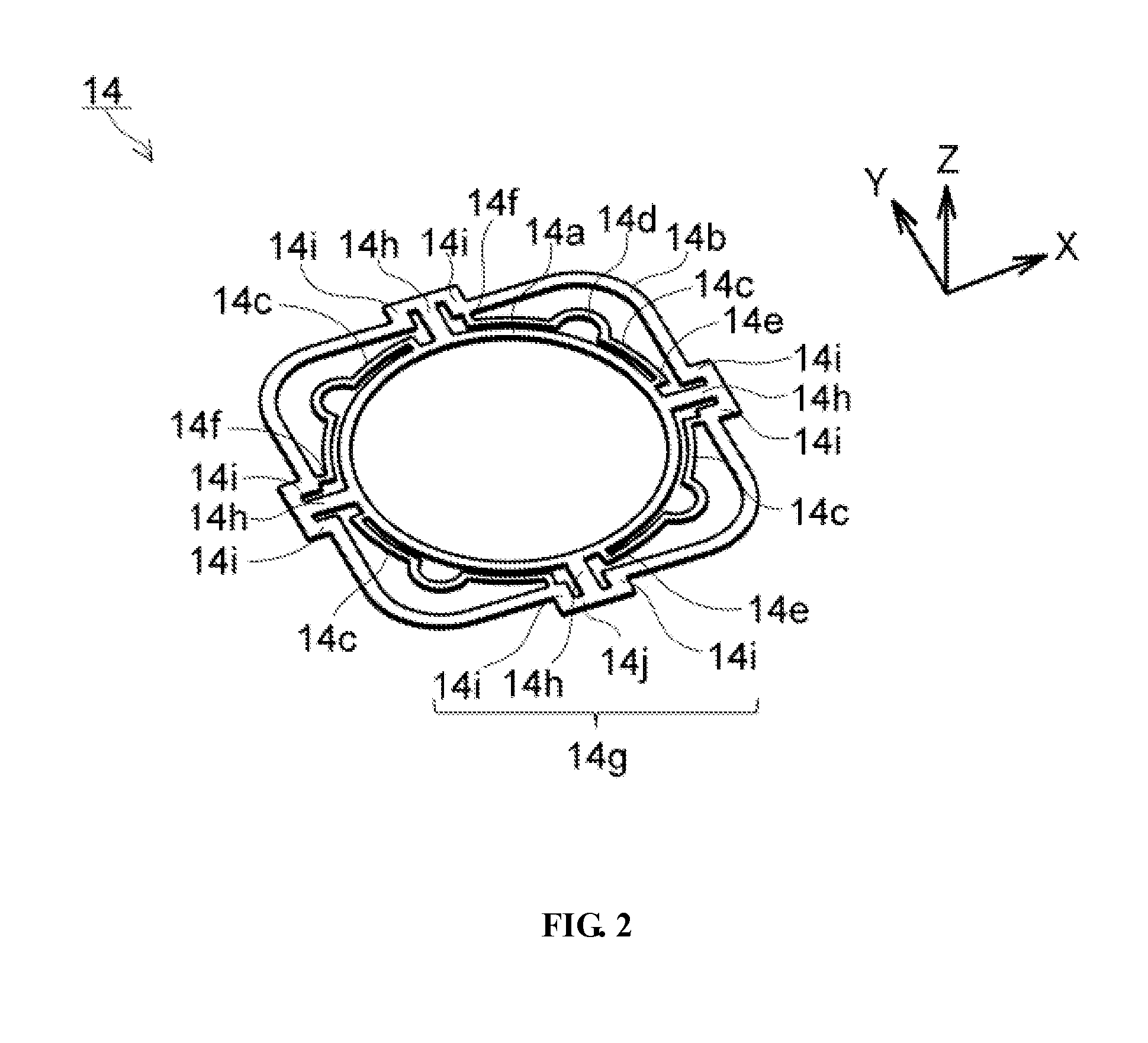
[0065]FIG. 1A and FIG. 1B are respectively perspective views illustrating an actuator unit 20 in according to a first embodiment of the present invention. FIG. 2 is a perspective view of a spring component 14, FIG. 3 is an exploded view of a lens driving device 10 assembled with the actuator unit 20 of the embodiment. FIG. 4A to FIG. 4D are cross-sectional views illustrating one example of the assembling working procedure of the actuator unit 20.

[0066]Moreover, in the Specification, the Z-axis direction is taken as the optical axis direction of a lens 11, the side of an object is taken as the f...


PUM


Abstract

The present invention aims to provide an actuator unit. When the actuator unit is assembled in a lens driving device and works, a lens support beginning to move cannot be inclined. A spring component (14) is provided with an inner side retaining part (14a), an outer side retaining part (14b), a plurality of wrist parts (14c), a plurality of inner side connecting parts (14e), a plurality of outer side connecting parts (14f) and spoke parts (14g) for connecting the inner side retaining part (14a) with the outer side retaining part (14b) in a releasable manner, wherein the lens support (17) is supported by the spring components (14), and an electromagnetic driving mechanism (22) is utilized for enabling the lens support (17) to move.

Description

CROSS-REFERENCE TO RELATED APPLICATIONS[0001]This application claims priority to Japanese patent application No. 2013-187281, filed on Sep. 10, 2013, contents of which are incorporated by reference herein.BACKGROUND OF THE INVENTION[0002]1. Field of the Invention[0003]The present invention relates to an actuator unit which is mounted on a lens driving device and utilizes an electromagnetic driving mechanism to enable a lens support supported by a spring component in a suspended manner to move.[0004]2. Description of Related Art[0005]FIG. 14A and FIG. 14B are diagrams illustrating an example of an existing voice coil motor type lens driving device 30.[0006]As shown in FIG. 14A, the lens driving device 30 is formed to be box-shaped and is composed of an actuator unit 40, a magnet yoke 32 for storing the unit, and a base 39. The actuator unit 40 arranged on the inner side of the magnet yoke 32 is utilized to enable a lens 31 to move towards the front of Z axis (+Z axis direction) or th...

Claims


Application Information

Patent Timeline
Patent Type & Authority Applications(United States)
IPC IPC(8): G02B7/04H02K41/035
CPCH02K41/0356G02B7/04G02B7/026G02B7/08
Inventor TERAJIMA, KOKICHI
Owner HUIZHOU DAYAWAY EVER BRIGHT ELECTRONICS IND CO LTD
Why Eureka
Try Eureka