Turbine blade

Inactive Publication Date: 2015-03-12
SIEMENS AG
View PDF20 Cites 3 Cited by
  • Summary
  • Abstract
  • Description
  • Claims
  • Application Information

AI Technical Summary

Benefits of technology

[0030]In order that the turbine blade may be inserted with the inner platform part and the outer platform part into the form of the endless platform frame gripping around the inner platform part, even in the case

Problems solved by technology

Turbine blades used in static turbomachines are subjected, in operation, to a multiplicity of loads which cause the turbine blades to age and wear both in foreseeable and non-foreseeable ways.
Nonetheless, wear phenomena such as cracks can appear in various regions of the turbine blade and end

Method used


Image

  • Turbine blade
  • Turbine blade
  • Turbine blade

Examples


Example

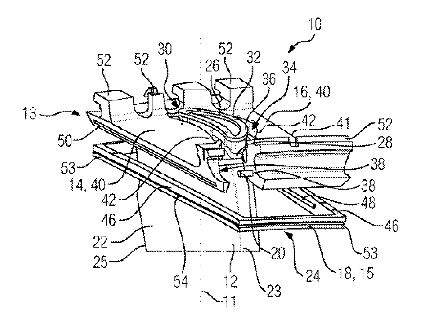
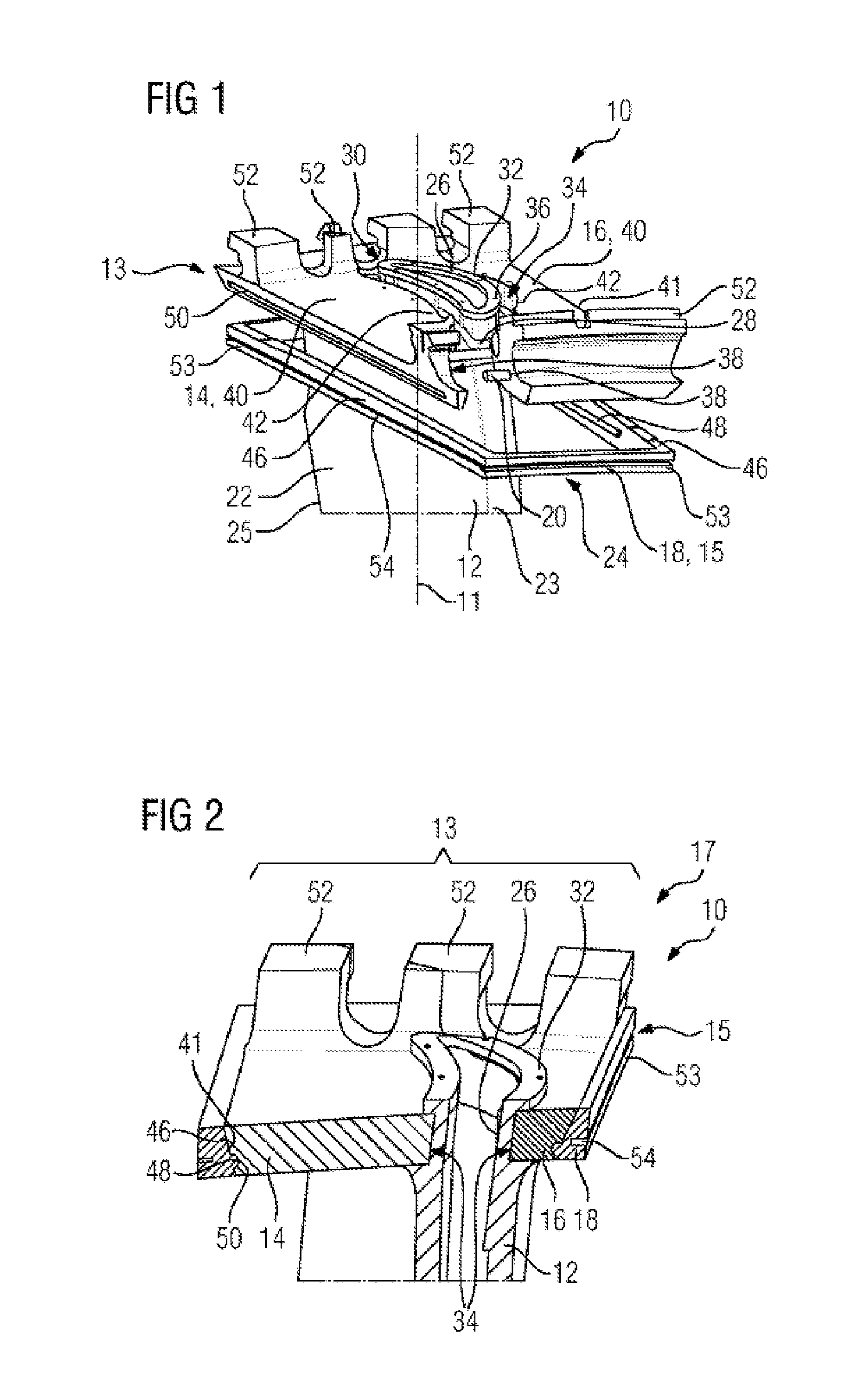
[0037]In all figures, identical features are provided with identical reference signs.

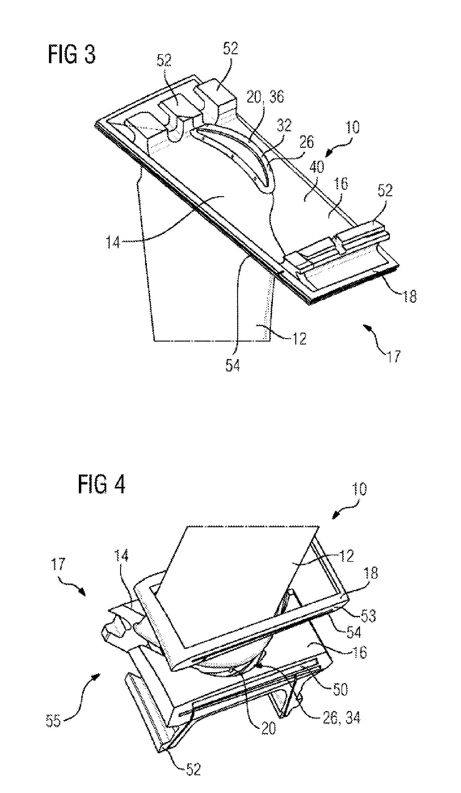
[0038]FIG. 1 shows part of a turbine blade 10 in the manner of an exploded drawing. The turbine blade 10 is of modular configuration and, according to this exemplary embodiment, therefore comprises as separately manufactured components a blade airfoil 12, two platform elements 14, 16 and a platform frame 18 and a plurality of bolts 20 connecting these to one another.

[0039]Moreover, the turbine blade 10 comprises a virtual longitudinal axis 11.

[0040]The blade airfoil 12 is curved aerodynamically and has, as is known, a pressure side 22 and a suction side 24. The pressure side 22 and the suction side 24 connect at a leading edge 23 and at a trailing edge 25. During designated use within a turbomachine, a working medium flows from the leading edge 23 to the trailing edge 25.

[0041]At the upper end, shown in FIG. 1, of the blade airfoil 12, there is provided a projection 26 which is formed in one piece w...


PUM


Abstract

A turbine blade is provided having a blade and a modular platform which follow one another along a longitudinal axis of the turbine blade. In order to provide a modular turbine blade that has an especially plain and simple design and that ensures an especially reliable, long-lasting, durable connection of the individual components among each other, the blade has an extension and the platform has an outer platform part and an at least two-part inner platform part which is radial in relation to the longitudinal axis and which lie laterally against the extension of the blade, and the outer platform part is designed as an endless platform frame that surrounds the outer edge of the inner platform part.

Description

CROSS REFERENCE TO RELATED APPLICATIONS[0001]This application is the US National Stage of International Application No. PCT / EP2013 / 056652 filed Mar. 28, 2013, and claims the benefit thereof. The International Application claims the benefit of European Application No. EP12162106 filed Mar. 29, 2012. All of the applications are incorporated by reference herein in their entirety.FIELD OF INVENTION[0002]The invention relates to a turbine blade having a platform and a blade airfoil in direct succession along a longitudinal axis of the turbine blade.BACKGROUND OF INVENTION[0003]A great many types of turbine blades and methods for manufacturing turbine blades are known from the extensive available prior art. For example, turbine blades for gas turbines are often manufactured by casting. In casting, the blade root, platform and blade airfoil are simultaneously formed from the casting material, such that turbine blades of this type are one-piece. Subsequently, those surfaces which are expose...

Claims


Application Information

Patent Timeline
IPC IPC(8): F01D5/30F01D5/08
CPCF01D5/08F01D5/30F01D5/147F01D9/042F01D11/006F05B2240/80F05D2240/80
Inventor AHMAD, FATHIBOLMS, HANS-THOMASKURT, NIHAL
Owner SIEMENS AG
Why Eureka
Try Eureka