Fluid displacement system using gerotor pump

a gerotor pump and fluid displacement technology, applied in the direction of positive displacement liquid engines, piston pumps, liquid fuel engines, etc., can solve the problems of significant power waste, impaired ability of centrifugal pumps to handle fluids, and unsatisfactory flow rates from wells, and achieve high viscosity hydrocarbons

Inactive Publication Date: 2015-03-12
INTREVEP SA
View PDF3 Cites 14 Cited by
  • Summary
  • Abstract
  • Description
  • Claims
  • Application Information

AI Technical Summary

Problems solved by technology

In other instances, the fluids can have an extremely high viscosity, or formation pressure may be too low, or numerous other factors can lead to unsatisfactory flow rates from the well.
In fact, each of these systems has issues when needed to operate on highly viscous hydrocarbons such as the heavy and extra heavy crude oils which are contained in the Orinoco Oil Belt.
The ability of centrifugal pumps to handle fluids is impaired by high viscosity.
A significant amount of power is wasted due to the low mechanical energy conversion capacity of centrifugal pumps.
It is possible to achieve larger flow rates but at the expense of using cumbersome, visually unpleasant and expensive surface driving units such as giant walking beams and power cylinders with necessary hydraulic power units.
Furthermore, clever as it is, converting rotational motion from prime motor to reciprocating motion to drive the downhole pump implies wasted energy due to incessant acceleration and deceleration of large mechanical parts such as rod strings and surface units.

Method used


Image

  • Fluid displacement system using gerotor pump
  • Fluid displacement system using gerotor pump
  • Fluid displacement system using gerotor pump

Examples


Embodiment Construction

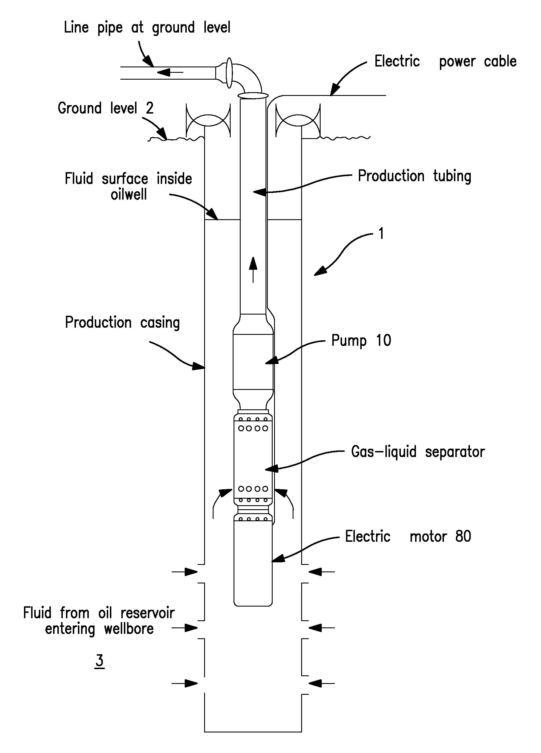
[0023]The invention relates to a fluid displacement system and method which utilizes gerotor pumps to improve pumping flow rates of heavy and extra heavy crude oils from subterranean wells.

[0024]FIG. 1 illustrates a subterranean well 1 extending from the surface 2 to a subterranean formation 3. Formation 3 is typically a permeable formation containing fluids within the void space of the formation, and it is desired to produce these fluids from the formation 3 through well 1 to surface 2.

[0025]While useful with a variety of potential different applications, the present invention is particularly well suited for use in producing heavy and extra heavy crude oils such as the heavy crude oil contained in the Orinoco Oil Belt. A typical hydrocarbon from this belt has a viscosity of about 1,000 cP at reservoir temperature (130-140° F.), and this type of fluid is very difficult to pump utilizing conventional sucker-rod pumps, progressing cavity pumps and the like.

[0026]In accordance with the...


PUM


Abstract

A fluid displacement system for a fluid producing subterranean well includes a well extending from a surface to a subterranean fluid bearing formation, the formation being in fluid communication with the well; and a gerotor pump in the well for pumping fluid from the formation to the surface.

Description

BACKGROUND OF THE INVENTION[0001]The invention relates to a system and method for pumping fluids from a subterranean well.[0002]Subterranean wells are commonly used for producing fluids such as hydrocarbons and the like from deep underground formations bearing such fluids. In some instances these fluids are sufficiently free-flowing and under sufficient pressure that production through the well to the surface does not need to be assisted. In other instances, the fluids can have an extremely high viscosity, or formation pressure may be too low, or numerous other factors can lead to unsatisfactory flow rates from the well.[0003]Various pumping methods have been used to increase flow from wells including sucker-rod pumps, progressing cavity pumps and electric submersible centrifugal pumps. In fact, each of these systems has issues when needed to operate on highly viscous hydrocarbons such as the heavy and extra heavy crude oils which are contained in the Orinoco Oil Belt.[0004]The abil...

Claims


Application Information

Patent Timeline
Patent Type & Authority Applications(United States)
IPC IPC(8): F04C23/02
CPCF04C23/02F04C2/102F04C11/001F04C13/008F04C2240/52
Inventor VAZQUEZ, RAIMUNDO PARDOSANDGREN, SERGIO ARTURO CAICEDOANEZ, ALEXANDRA DEL CARMEN ARAUJO
Owner INTREVEP SA
Why Eureka
Try Eureka