
Reversing Switch

a reverse switch and switch technology, applied in the direction of contact electric connection, contact electrical connection, electrical apparatus, etc., can solve the problems of affecting the working performance of the switch, and achieve the effects of poor shock resistance and vibration resistance, easy heat generation, and large internal resistan

Inactive Publication Date: 2015-03-19
SHANGHAI BAICHENG ELECTRONICS
View PDF4 Cites 0 Cited by
  • Summary
  • Abstract
  • Description
  • Claims
  • Application Information

AI Technical Summary

Benefits of technology

The present disclosure provides a reversing switch that overcomes the technical problem of a reversing loop with high internal resistance, poor shock and vibration resistance, and easy generation of heat. The reversing switch has input and output terminals connected through multiple reversing connectors that are synchronously moved. The increased contact area between the input and output terminals reduces contact resistance and improves current loading capability, ensuring reliable contact even at high power loads. Additionally, the increased number of contacts effectively resists the effects of shock and vibration on switch performance.

Problems solved by technology

Further, in the energized state, the switch will bear certain impact and vibration inevitably, and the single connection contact point will cause loose contact of the contact part easily so that the working performance of the switch will be affected because of the severe heat.

Method used


Image

  • Reversing Switch
  • Reversing Switch
  • Reversing Switch

Examples


Embodiment Construction

[0026]The embodiments of the present disclosure will be described in details below in combination with the accompanying drawings, but the present disclosure may be implemented by various different methods limited and covered by the claims.

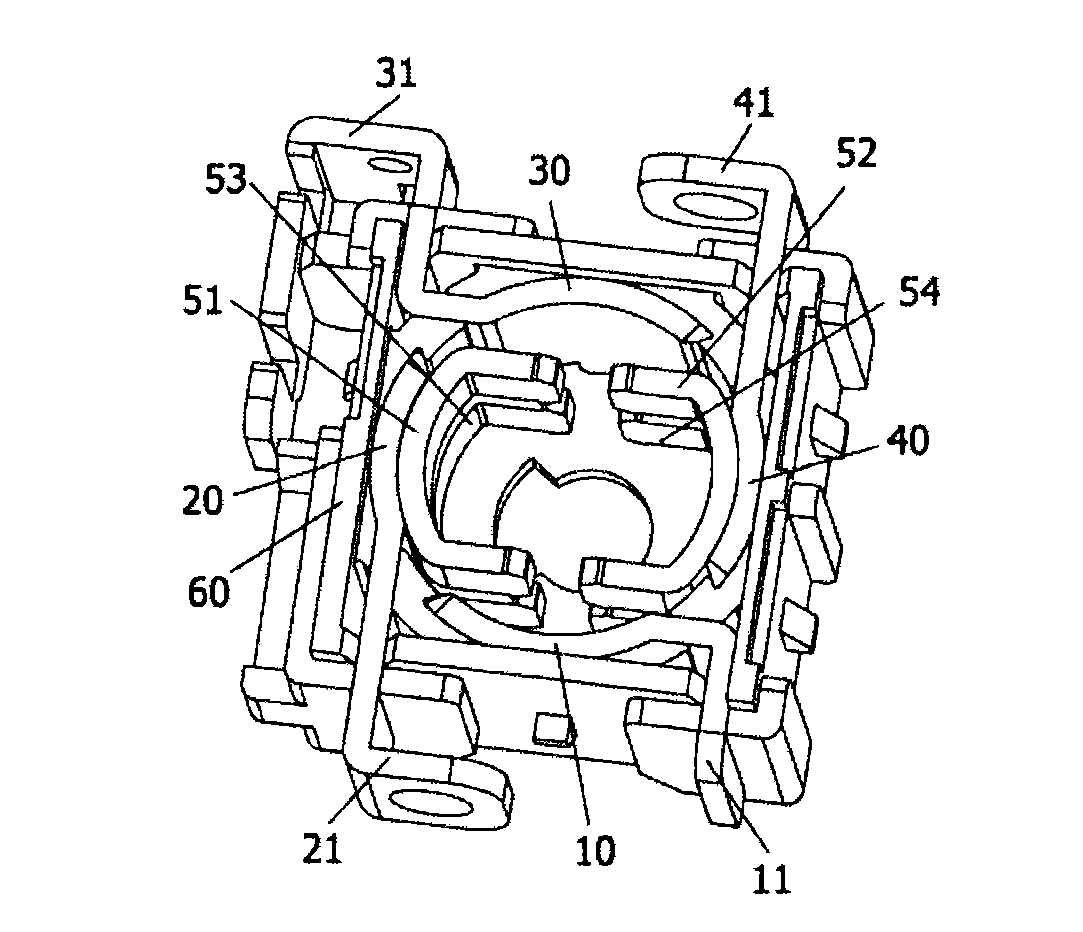
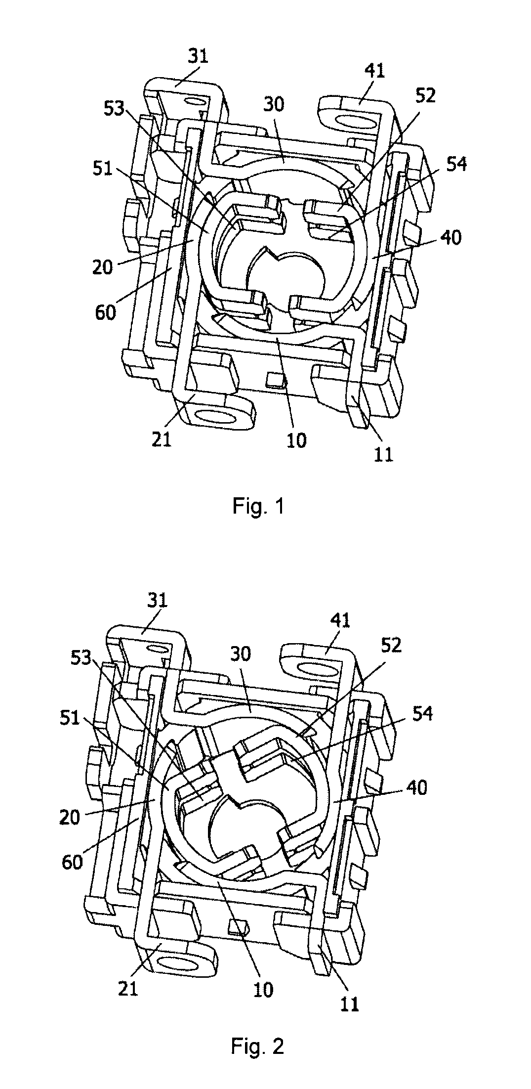
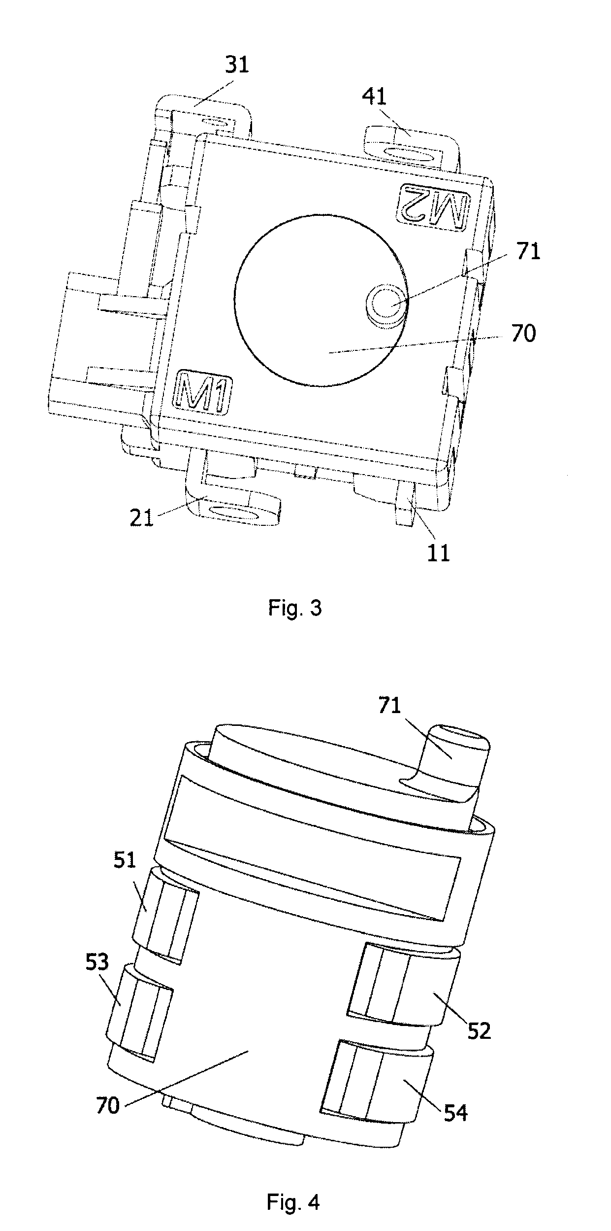
[0027]As shown in FIG. 1, FIG. 2 and FIG. 3, the present disclosure provides a reversing switch, which includes a switch body 60, and input terminals and output terminals independent from each other and provided in pairs on the switch body 60. Each pair includes one input terminal and one output terminal. One of the input terminals is connected or disconnected to one of the output terminals via a plurality of independent reversing connectors, and the plurality of independent reversing connectors are configured to be movable synchronously. The plurality of independent reversing connectors are adopted between the input terminals and the output terminals of the reversing switch provided by the present disclosure to realize the connection and the disco...


PUM


Abstract

The present disclosure provides a reversing switch, including a switch body, and input terminals and output terminals independent from each other and provided in pairs on the switch body; each pair comprising one input terminal and one output terminal; wherein one of the input terminals is connected or disconnected with one of the output terminals via a plurality of independent reversing connectors, and the plurality of independent reversing connectors are configured to be movable synchronously. A plurality of independent reversing connectors are adopted between the input terminals and the output terminals of the reversing switch provided by the present disclosure to realize the connection and the disconnection between the input terminal and the output terminal, thus increasing the contact area between the reversing connectors and the input terminals or the output terminals, reducing the contact resistance, and improving the current loading capability of the reversing switch. In the meanwhile, the contact reliability could be ensured when the reversing switch is powered on because the number of contacts is increased, thereby effectively resisting the affection on the switch performance by shock and vibration.

Description

TECHNICAL FIELD OF THE INVENTION [0001]The present disclosure relates to the field of switch technology of electrical system, and more particularly to a reversing switch.BACKGROUND OF THE INVENTION [0002]Currently, there are basically two major types of positive and negative rotation mechanisms adopted by the reversing switch on the market:[0003]The first type is an electronic positive and negative rotation mechanism, which realizes the function of positive and negative rotation of a motor through connection of electronic circuits.[0004]The second type is a mechanical positive and negative rotation mechanism, which realizes the function of positive and negative rotation of a motor through connection of mechanical structures.[0005]The former type is rarely applied because of high cost, while the latter type is widely applied because of lower cost and easy implementation.[0006]Wherein, the mechanical positive and negative rotation mechanism further includes a side contact type: relati...

Claims


Application Information

Patent Timeline
IPC IPC(8): H01H1/50H01H1/58H01H9/06
CPCH01H1/50H01H1/58H01H9/063H01H19/08H01H19/56
Inventor CAI, YINGJIE
Owner SHANGHAI BAICHENG ELECTRONICS
Learn More