Accumulator arrangement

a technology of accumulator and accumulator plate, which is applied in the direction of nickel accumulator, sustainable manufacturing/processing, nickel accumulator, etc., can solve the problems of long use periods at a high energy consumption, inability to fully exploit the capacity of the accumulator, and even increase the problem of problems, so as to achieve cost saving, small internal resistance, and large internal resistance

Inactive Publication Date: 2008-01-10
HOPPECKE BATTERIEN
View PDF7 Cites 5 Cited by
  • Summary
  • Abstract
  • Description
  • Claims
  • Application Information

AI Technical Summary

Benefits of technology

[0032] Additionally, it is proposed that the state variable is memorized. In this way the state variable can be kept available for interrogation. This embodiment is particularly advantageous in mobile applications, where the accumulator arrangement is not accessible during its operation as intended.
[0033] It is further proposed that the state variable is transmitted to a central terminal. The transmission can take place for instance via radio or the like. In this way the central terminal can keep the state variable of the accumulator arrangement and initiate measures upon reaching predetermined thresholds. Accordingly, it can be provided that if the charging state drops below a predetermined charging condition of the accumulator arrangement of a vehicle, the accumulator arrangement must either be replaced for a charged accumulator arrangement or recharged as soon as possible.
[0034] According to a further development it is provided that the accumulator with the small internal resistance is charged by the accumulator with the large internal resistance. Thereby it can be achieved that the capacity for the accumulator with the small internal resistance can be kept smaller than the capacity for the accumulator with the large internal resistance. Costs can be saved.
[0035] In a further embodiment it is provided that the discharging and / or charging of the accumulators is controlled by means of a control unit. In a traction vehicle the accumulator with the large internal resistance is provided for the base load operation and the high power accumulator with the small internal resistance is provided for peak loads. To this end the control unit includes a current measuring unit and provides for the preservation of a minimum charge for reaching the next charging station. It is made possible thereby not only to achieve the optimum availability of the accumulator arrangement but each accumulator arrangement can also be charged optimally according to its characteristic. A high reliability throughout the intended service life can be reached.
[0036] Moreover, it is provided that the discharging and / or charging of the accumulators is controlled in dependence of the state variable. It can be provided for instance that in the case of a value dropping below a voltage threshold or a charge threshold of the accumulator or the accumulator arrangement the charging of the accumulators or the accumulator arrangement is caused. The availability of the accumulator arrangement can be further improved.

Problems solved by technology

In addition, batteries or accumulators are used in places where public energy supply is available not at all or only with insufficient reliability.
Accumulators are especially used for mobile applications where the multiple use thereof, which is made possible by recharging, allows long periods of use also at a high energy consumption.
But a disadvantage in these accumulators is that caused by a comparatively high internal resistance which is dependent of the charging state the capacity of the accumulator cannot be completely exploited in the supply of an electric system connected to the accumulator, especially when high current loads occur at discharging conditions below approx 20% of the rated capacity.
In practice this disadvantage leads to the fact that if inexpensive accumulators are used the same must be over-dimensioned for the operation of the electrical system as intended in order to guarantee the operation of the connected electrical system as intended because this operation normally requires an appropriately constant voltage which is independent of the characteristic load and which is allowed to change only within a particular narrow voltage range.
In these accumulator arrangements the problems may even grow because the individual accumulators frequently have different characteristic parameters like aging state, internal resistance, capacity and the like.
And it's precisely the inexpensive accumulators which in addition to an already initially existing high internal resistance exhibit an increase in the internal resistance over the period of operation which is comparatively high and which clearly negatively influences the quality features of the accumulator arrangement.
Beyond, their characteristic values frequently spread over an undesirably vast range.
A disadvantage of this approach resides in the fact that additional and partly expensive electronic components are required and that energy is lost due to the voltage transformation.

Method used


Image

  • Accumulator arrangement
  • Accumulator arrangement

Examples


Embodiment Construction

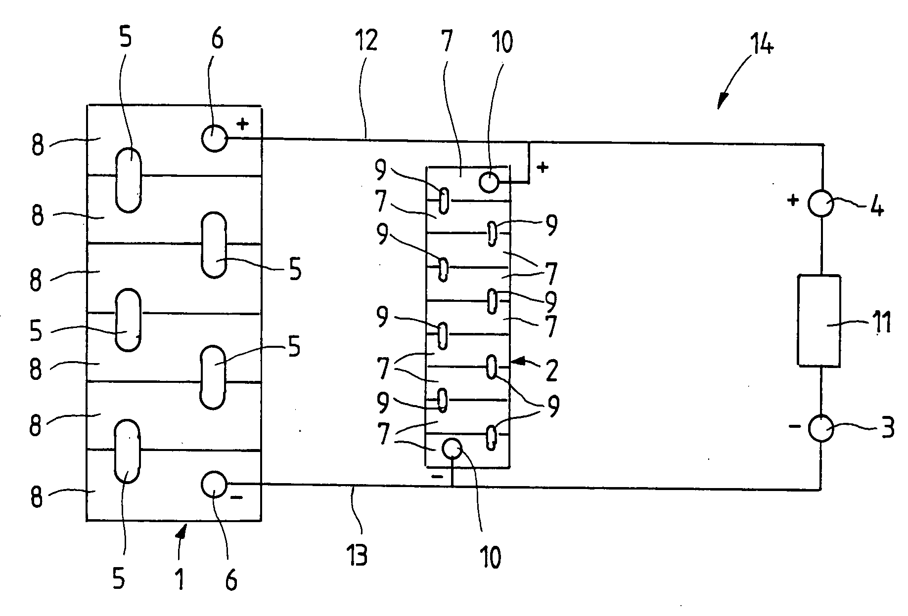
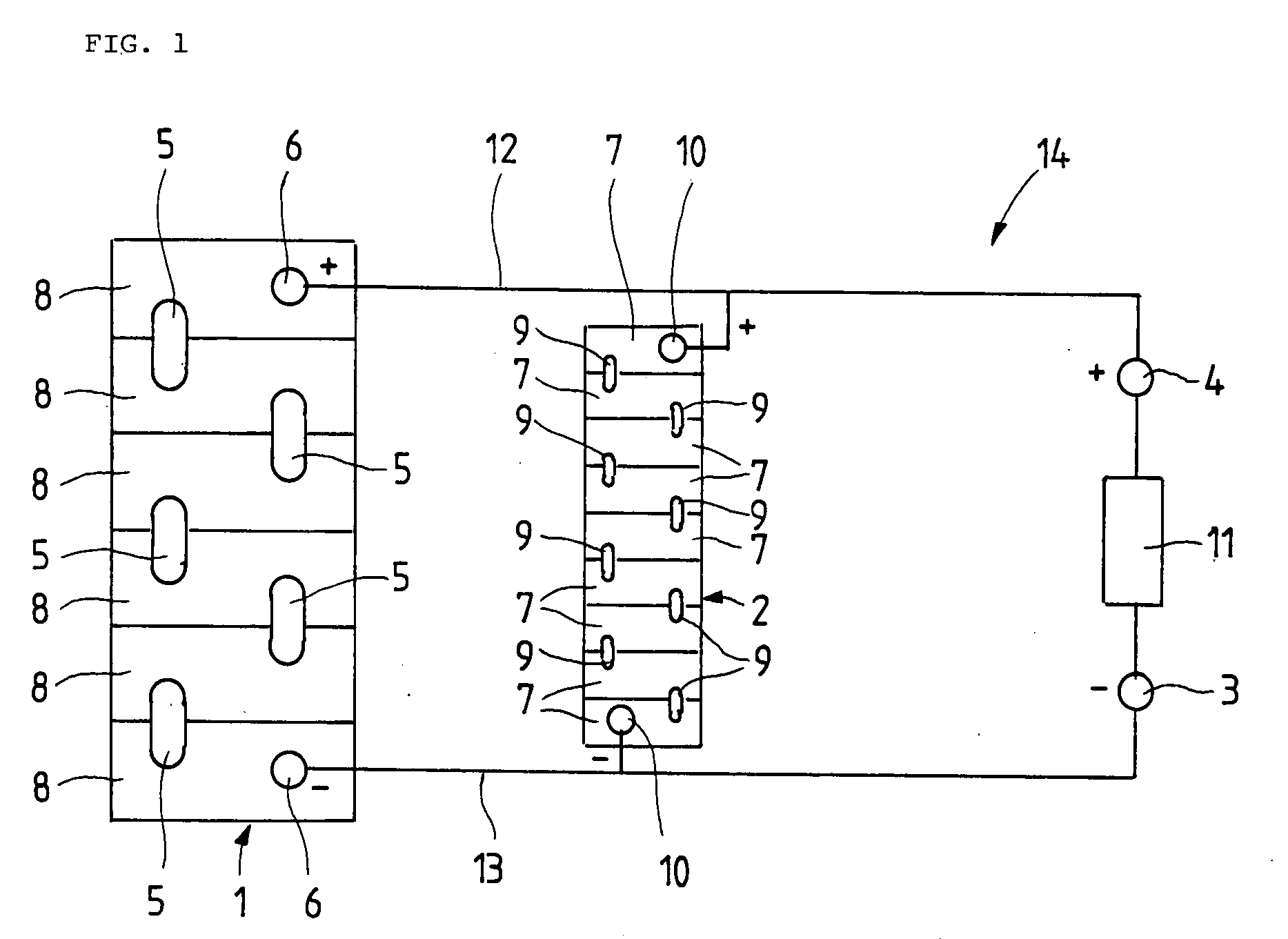
[0039] The single drawing figure shows a lead-acid accumulator using sulphuric acid as an acid. The lead-acid accumulator 1 consists of six series-connected accumulator cells 8, with the series connection being established by connecting the corresponding poles through electrically conductive bridges 5. The accumulator 1 includes two terminals 6, one each for the positive pole and the negative pole. The drawing figure further shows a nickel-cadmium accumulator 2 which is formed from nine cells 7. The cells 7 are electrically interconnected in series by means of bridges 9. The accumulator 2 has two terminals 10, one each for the positive pole and the negative pole. Through lines 12, 13 the positive poles 6, 10 of the accumulators 1, 2 are connected to the positive connection pole 4 of the accumulator arrangement 14. Correspondingly, the negative poles 6, 10 of the accumulators 1, 2 are connected to the negative connection pole of the accumulator arrangement 14. Accordingly, the two ac...


PUM


Abstract

The present invention relates to an accumulator arrangement with accumulators that can be operated in parallel, and also to a method for operating the accumulator arrangement according to the invention. The present invention is based on the problem of improving the exploitation of the capacity of an accumulator and of accumulator arrangements. As a solution the present invention proposes that the accumulator arrangement is configured in such a way that at least one lead-acid accumulator with a large internal resistance and at least one accumulator with a basic electrolyte respectively a sealed lead accumulator with a small internal resistance are operable in parallel.

Description

BACKGROUND [0001] 1. Technical Field [0002] The present invention relates to an accumulator arrangement with accumulators that can be operated in parallel and to a method for operating the accumulator arrangement according to the invention. [0003] 2. Discussion [0004] Batteries and especially accumulators are used in many technical fields and are particularly intended for a local energy supply of electric consumers. In addition, batteries or accumulators are used in places where public energy supply is available not at all or only with insufficient reliability. Accumulators are especially used for mobile applications where the multiple use thereof, which is made possible by recharging, allows long periods of use also at a high energy consumption. Accordingly, accumulators are frequently used in the traction operation as well as in the field of uninterruptible power supply, for instance in fork lifters, lifting devices, golf caddies or the like. Accumulators are also broadly used on ...

Claims


Application Information

Patent Timeline
Patent Type & Authority Applications(United States)
IPC IPC(8): H02J7/00
CPCH01M10/0525H01M10/06H01M10/48H01M10/345H01M10/441H01M10/30Y02E60/10Y02P70/50
Inventor RIEGEL, BERNHARDOHMS, DETLEFMARKOLF, RAINERCATTANEO, EDUARDO
Owner HOPPECKE BATTERIEN
Why Eureka
Try Eureka