Stacked film battery architecture

a film battery and structure technology, applied in the field of film battery structure, can solve the problems of small internal resistance, small stfb energy capacity, and difficult thickening of stfb, and achieve the effects of good bonding quality, reduced mechanical damage on the film battery element, and high selectivity

Active Publication Date: 2018-03-22
IBM CORP
View PDF2 Cites 14 Cited by
  • Summary
  • Abstract
  • Description
  • Claims
  • Application Information

AI Technical Summary

Benefits of technology

[0008]The stacked battery structure fabricated by the method according to an embodiment of the present invention can have an improved battery characteristic (e.g., large capacity, small internal resistance and / or high voltage depending on a mode of connection) while maintaining small footprint and reducing internal mechanical stress. Since each battery layer prepared for stacking has the film battery element that is already fabricated, other components of the stacked battery structure would not be damaged due to heating process for fabricating the film battery element.
[0018]The stacked battery structure according to an embodiment of the present invention can have an improved battery characteristic while maintaining small footprint and reducing internal mechanical stress. Since the stacked solid battery layers are shifted and the surface of each current collector are exposed to the through via, reliable contact between the through via and the current collectors of the film battery layers can be archived. Also since connection between the plurality of battery layers are made by the through via formed within the plurality of battery layers, the stacked battery structure would have space-saving layout.

Problems solved by technology

However, the small STFB does not have enough energy capacity and small internal resistance.
Thickening of the STFB is known to be technically difficult.
However, since a solid electrolyte used for STFB such as lithium phosphorus oxynitride (LiPON) is known to be brittle, stacking may be required to be performed under low mechanical stress conditions.
Even nominal mechanical stress on an electrode / electrolyte interface would cause damage on the solid electrolyte, which leads to short circuit.
Furthermore, cathode materials, such as LiCoO2, may require a high temperature annealing process, which makes sequential stacking difficult from a view point of heat resistance of other components.
However, such stacked structure would not be suitable for miniaturization since the trays each receiving prepackaged solid state battery are stacked.

Method used


Image

  • Stacked film battery architecture
  • Stacked film battery architecture
  • Stacked film battery architecture

Examples


Embodiment Construction

[0031]The present invention will be described using particular embodiments, and the embodiments described hereafter are understood to be only referred as examples and are not intended to limit the scope of the present invention.

[0032]One or more embodiments according to the present invention are directed to a stacked battery structure, a method for fabricating the stacked battery structure and an electronic device including the stacked battery structure, in which a plurality of film battery elements is arranged in a stacked manner.

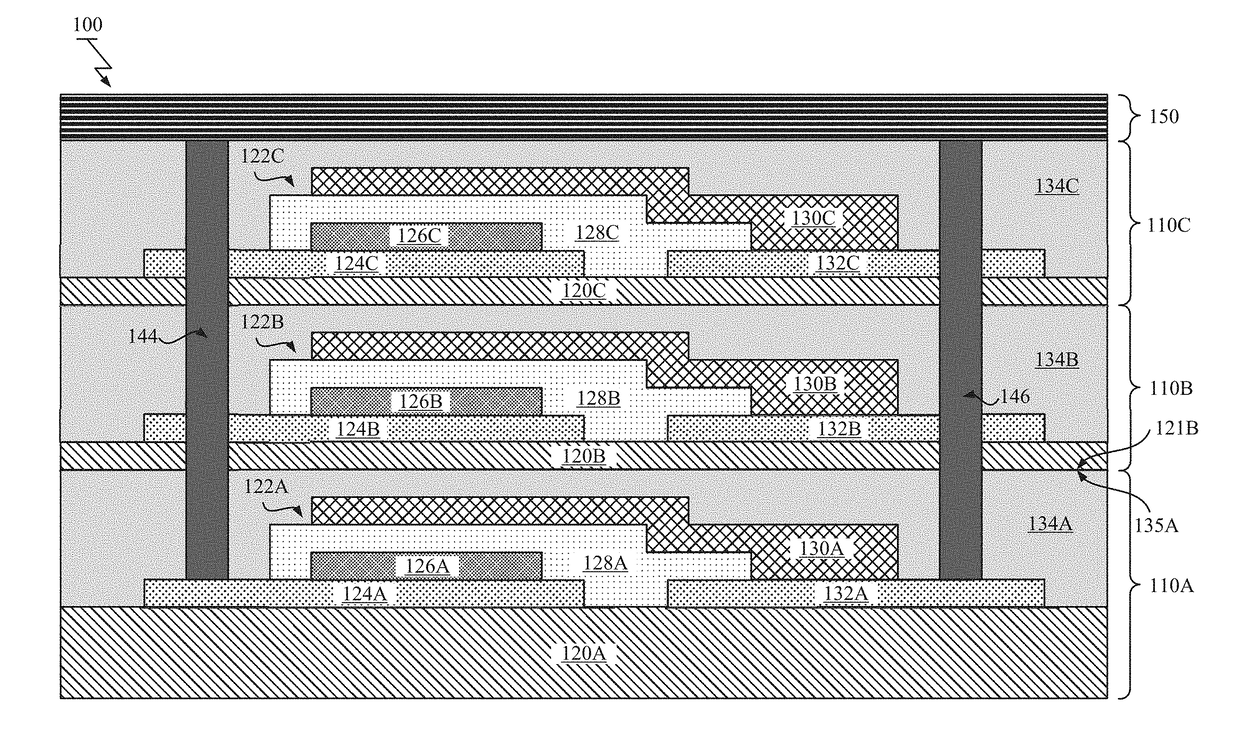
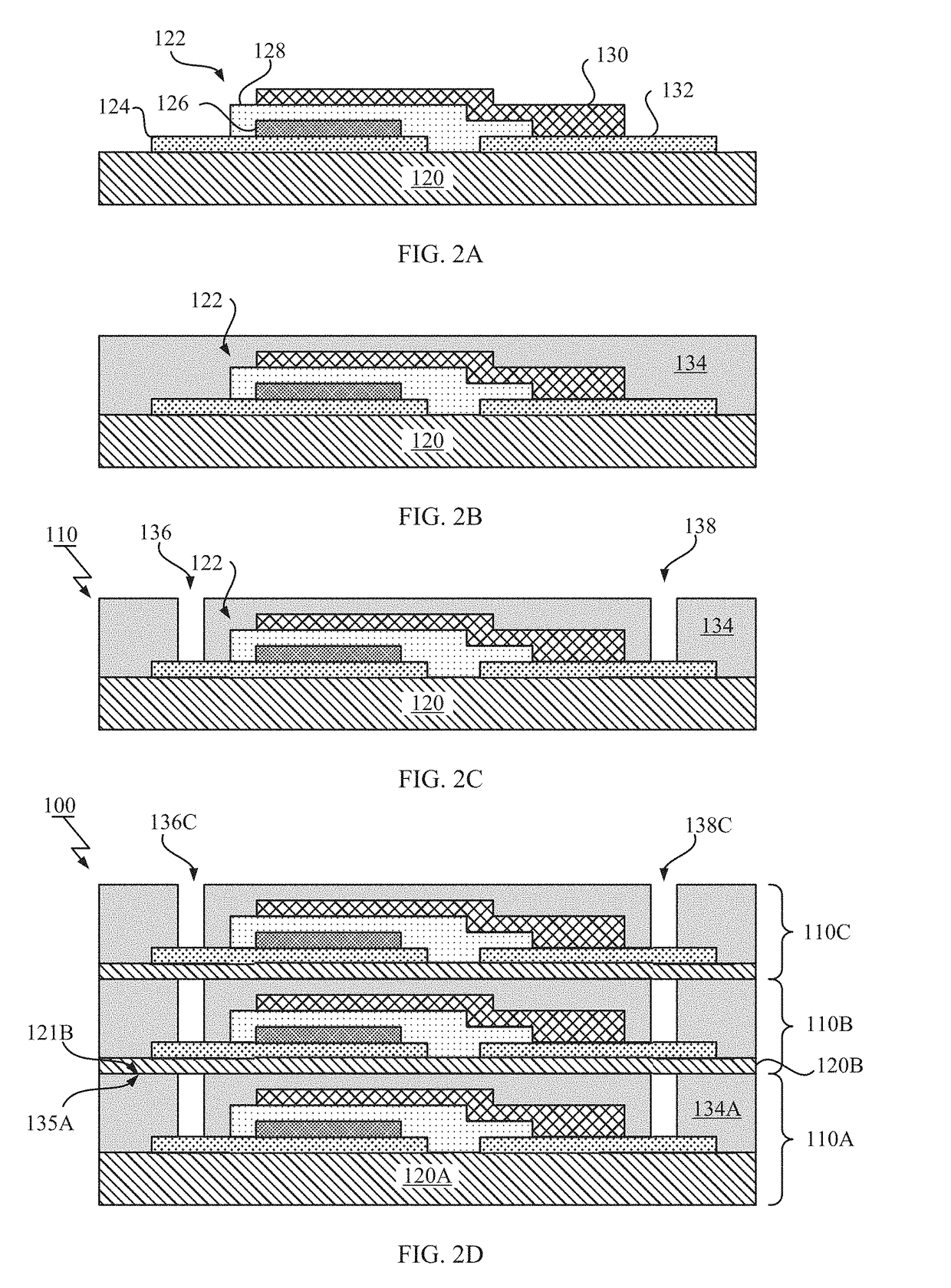
[0033]Hereinafter, referring to FIG. 1, it will be described a schematic of a stacked battery structure 100 according to an exemplary embodiment of the present invention.

[0034]FIG. 1 illustrates a cross-sectional view of the stacked battery structure 100. As shown in FIG. 1, the stacked battery structure 100 may include two or more stacked battery layers 110 (e.g., layers 110A-110C), a pair of through vias 144, 146 formed within the stacked battery layers ...


PUM

PropertyMeasurementUnit
temperatureaaaaaaaaaa

Abstract

A method for fabricating a stacked battery structure. The method includes preparing a plurality of battery layers separately, wherein each battery layer includes a substrate, a film battery element fabricated on the substrate and an insulator formed over the film battery element. The insulator has a flat top surface and the film battery element includes a current collector. The method also includes stacking the plurality of battery layers, wherein the insulator of a first battery layer of the plurality of battery layers bonds to the substrate of a second battery layer of the plurality of battery layers by the flat top surface. The method further includes forming a conductive path within the plurality of battery layers, wherein the conductive path connects with at least one of the current collectors of the plurality of battery layers.

Description

BACKGROUNDTechnical Field[0001]The present invention, generally, relates to battery technology and, more particularly, to stacked battery structures and methods for fabricating thereof.Description of the Related Art[0002]In response to demand for miniaturization of computing systems, millimeter scale computing systems have been developed. To achieve a small computing system, which may be used for Internet of Things (IoT) devices, one of the concerns is its power sources. The small computing system may require a small footprint battery.[0003]Recently, a solid thin film battery (STFB) has been attracted as one of promising batteries for the IoT devices in terms of its small footprint and safety attribute. However, the small STFB does not have enough energy capacity and small internal resistance. The STFB can be enlarged by ingenious spattering techniques to increase its energy capacity, but its footprint becomes larger. Thickening of the STFB is known to be technically difficult.[0004...

Claims


Application Information

Patent Timeline
Patent Type & Authority Applications(United States)
IPC IPC(8): H01M10/04H01M10/0525H01M10/0562H01M4/04H01M4/131H01M4/505H01M4/485H01M4/58H01M10/0585
CPCH01M10/0436H01M10/0525H01M10/0562H01M4/043H01M4/0402H01M4/04H01M2300/0068H01M4/505H01M4/485H01M4/58H01M4/045H01M10/0585H01M2300/0071H01M4/131H01M4/0492H01M6/40Y02E60/10Y02P70/50
Inventor HORIBE, AKIHIROSUEOKA, KUNIAKI
Owner IBM CORP
Why Eureka
Try Eureka