
Separating membrane for fuel cell

a fuel cell and membrane technology, applied in the field of membranes for fuel cells, can solve the problems of high fuel cell output reduction, polymer poisoning of catalysts, etc., and achieve the effect of large molecular weight and high outpu

Inactive Publication Date: 2011-04-12
TOKUYAMA CORP
View PDF9 Cites 15 Cited by
  • Summary
  • Abstract
  • Description
  • Claims
  • Application Information

AI Technical Summary

Benefits of technology

The solution results in improved bonding between the electrolyte membrane and catalyst electrode layer, reducing internal resistance and maintaining high fuel cell output voltage over a prolonged period by preventing catalyst poisoning.

Problems solved by technology

Even with such a membrane, however, there are cases that the high output of fuel cell reduces when the use period of fuel cell is prolonged.
The fuel dissolving the polymer fraction diffuses into the catalyst electrode layer, causing the poisoning of catalyst by polymer.

Method used

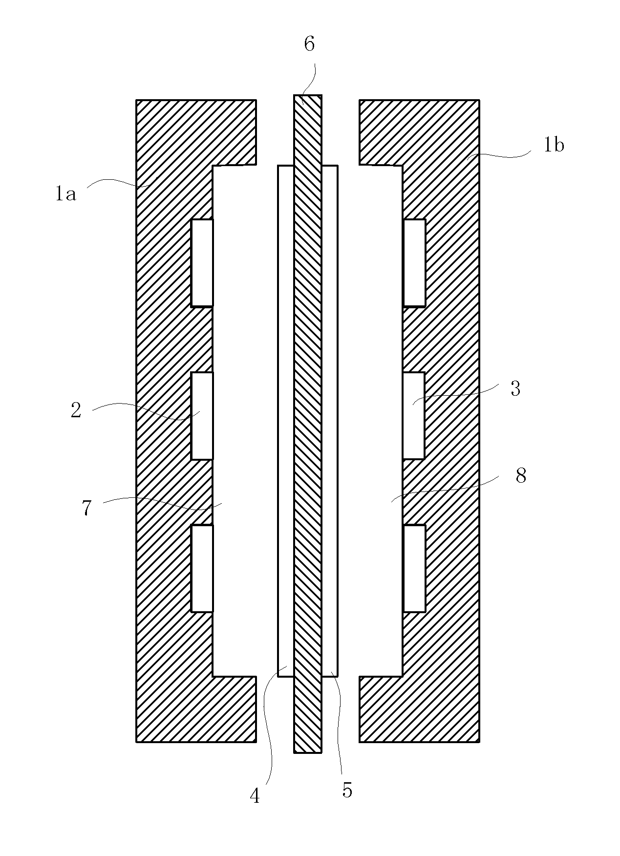
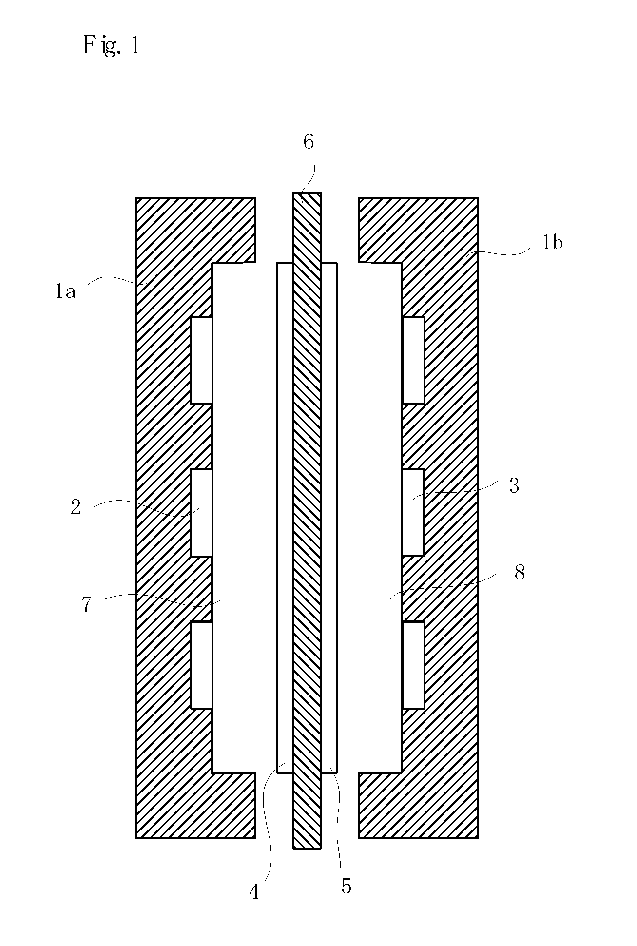

Image

  • Separating membrane for fuel cell
  • Separating membrane for fuel cell

Examples


production example 1

[0167]There was prepared a monomer composition consisting of 100 parts by mass of styrene, 10 parts by mass (8.0 mole % in total polymerizing monomers) of divinylbenzene and 5 parts by mass of tert-butyl peroxyethylhexanoate. Therein was immersed, at atmospheric pressure at 25° C. for 10 minutes, a porous membrane (thickness: 25 μm, porosity: 37%, average pore diameter: 0.03 μm) made of a polyethylene (PE, weight-average molecular weight: 250,000), to impregnate the porous membrane with the monomer composition.

[0168]The porous membrane was taken out of the monomer composition and covered at the both sides with a 100-μm polyester film (a peeling material). Then, thermal polymerization was conducted under nitrogen pressure of 0.3 MPa at 80° C. for 5 hours.

[0169]The resulting filmy material was immersed, at 40° C. for 45 minutes, in a 1:1 mixture of 98% concentrated sulfuric acid and chlorosulfonic acid (purity: 90% or more), to obtain a sulfonic acid type cation exchange membrane. The...

production examples 2 to 4

[0170]Cation exchange membranes were obtained in the same manner as in Production Example 1 except that the monomer composition and porous membrane of Production Example 1 were changed to those shown in Table 1. The cation exchange membranes were measured for ion exchange capacity, water content, membrane resistance and membrane thickness. The results are shown in Table 2.

production example 5

[0171]The cation exchange membrane of Production Example 1 was dried at room temperature for 24 hours. Then, the dried cation exchange membrane was immersed, at room temperature for 30 minutes, in a monomer composition consisting of 100 parts by mass of 4-vinylpyridine, 80 parts by mass (39.0 mole % in total polymerizing monomers) of divinylbenzene, 5 parts by mass of tert-butyl peroxyethylhexanoate, 900 parts by mass of toluene and 200 parts by mass of pyridine.

[0172]The ion exchange membrane was taken out of the monomer composition and covered at the both sides with a 100-μm polyester film (a peeling material). Then, thermal polymerization was conducted under nitrogen pressure of 0.3 MPa at 80° C. for 5 hours. The resulting polymerization product was immersed in methanol for 2 hours to obtain a cation exchange membrane having also an anion exchange group.

[0173]The above cation exchange membrane was measured for cation exchange capacity, water content, membrane resistance and membr...


PUM

PropertyMeasurementUnit
thicknessaaaaaaaaaa
sizeaaaaaaaaaa
pore diameteraaaaaaaaaa

Abstract

The present invention discloses a membrane for a fuel cell, comprising: a solid polymer electrolyte membrane composed of a crosslinked ion exchange resin, and a polymer having a weight-average molecular weight of 5,000 to 1,000,000 and having a charge group of polarity opposite to that of the ion exchange group of the ion exchange resin, which polymer is adhered onto at least one surface of the solid polymer electrolyte membrane in an amount of 0.0001 to 0.5 mg / cm3, preferably in a state that, when the membrane for fuel cell is immersed in a 50 mass % aqueous methanol solution of 30° C., there is substantially no difference in the adhesion amount of the polymer before and after the immersion; and a membrane-electrode assembly for a fuel cell, comprising the above-mentioned membrane, and a catalyst electrode layer bonded to the membrane, which catalyst electrode layer contains an ion exchange resin having the same polarity as the crosslinked ion exchange resin composing the solid polymer electrolyte membrane, and a catalyst substance.

Description

TECHNICAL FIELD[0001]The present invention relates to a membrane for fuel cell, a process for production thereof, and a membrane-electrode assembly for fuel cell. Explaining in more detail, the present invention relates to a membrane for polymer electrolyte fuel cell, composed of a crosslinked ion exchange resin membrane, a process for production thereof, and a membrane-electrode assembly for fuel cell.BACKGROUND ART[0002]Ion exchange membrane is in wide use as a membrane for cell (e.g. polymer electrolyte fuel cell, redox flow cell or zinc-bromine cell), a membrane for dialysis, etc. Polymer electrolyte fuel cell using an ion exchange membrane as the electrolyte is an power generation system in which a fuel and an oxidizing agent are fed continuously, then they are reacted, and the resulting chemical energy is taken out as an electric power; and it is an power generation system which is clean and highly efficient. In recent years, this power generation system has increased its impo...

Claims


Application Information

Patent Timeline
Patent Type & Authority Patents(United States)
IPC IPC(8): H01M8/10C08J5/22
CPCH01M8/0291H01M8/1011H01M8/1025H01M8/1027H01M8/1039H01M8/1044H01M8/1067H01M8/1072H01M8/1088H01M8/103H01M4/921Y02E60/523H01M8/0289Y02E60/50Y02P70/50H01M8/02H01M8/10H01M4/86
Inventor FUKUTA, KENJISADASUE, KAZUYUKIKISHINO, MASAYUKI
Owner TOKUYAMA CORP
Learn More