Metabolic Simulator Having a Catalytic Engine

Inactive Publication Date: 2015-03-19
INGMAR MEDICAL
View PDF5 Cites 2 Cited by
  • Summary
  • Abstract
  • Description
  • Claims
  • Application Information

AI Technical Summary

Problems solved by technology

Usually, RER equals RQ but, in some cases, such as hyperventilation or intense exercise, estimating t

Method used


Image

  • Metabolic Simulator Having a Catalytic Engine
  • Metabolic Simulator Having a Catalytic Engine
  • Metabolic Simulator Having a Catalytic Engine

Examples


working examples

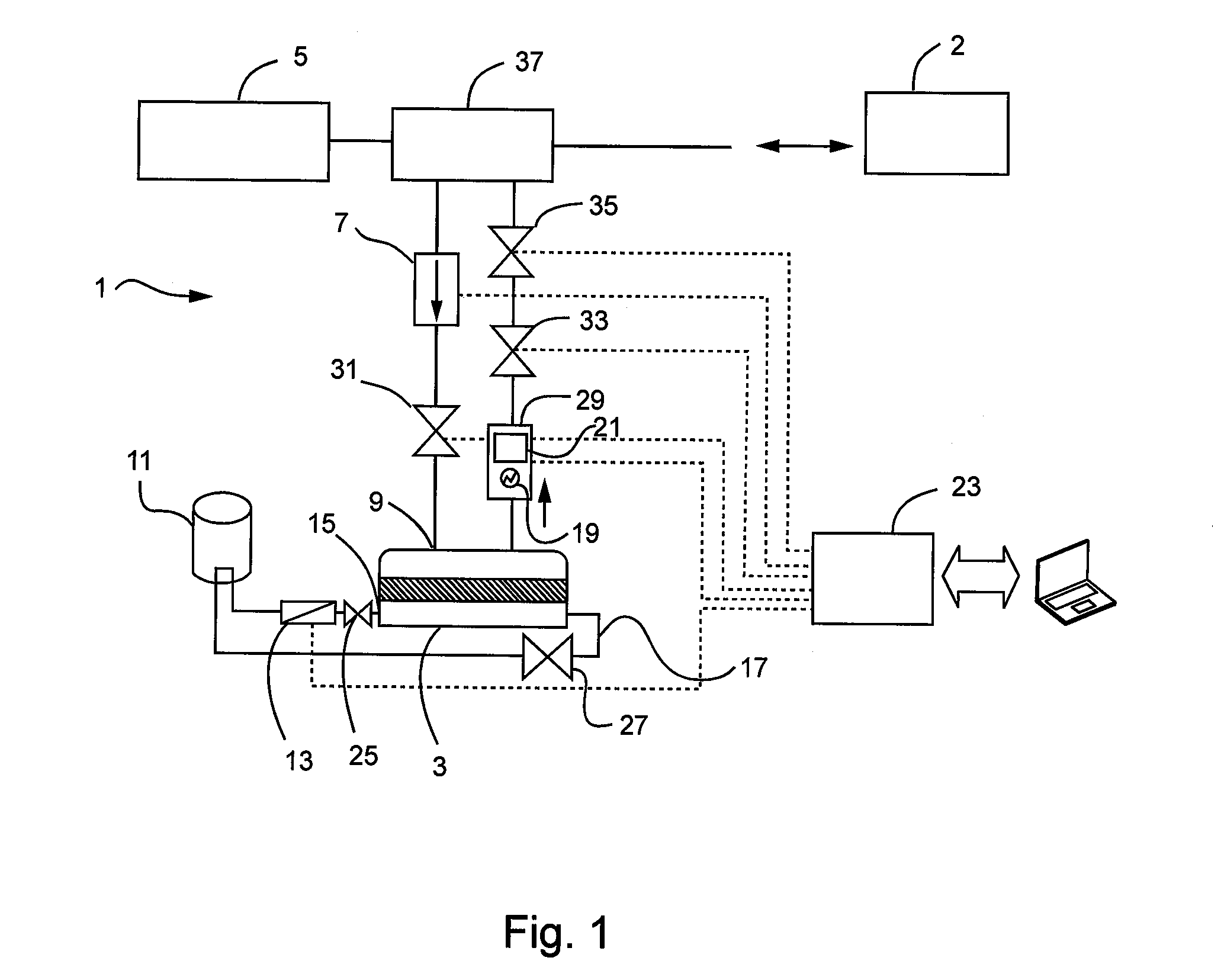
[0030]To make sure the test results reflected the catalytic carbon dioxide generator's 3 behavior, all of the tests were performed with the polisher disabled. The heated tubing was activated to prevent water condensation in the tubing. The fan speed on the cooler was set at 50% during all tests.

example 1

[0031]The fuel used in the first example consists of 99.8% methanol diluted in water. The molar concentration in the tests varied between 1 and 4 molar.

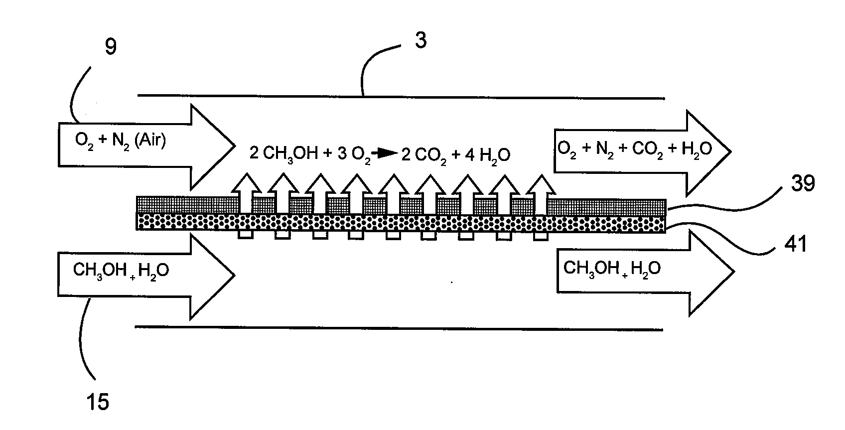
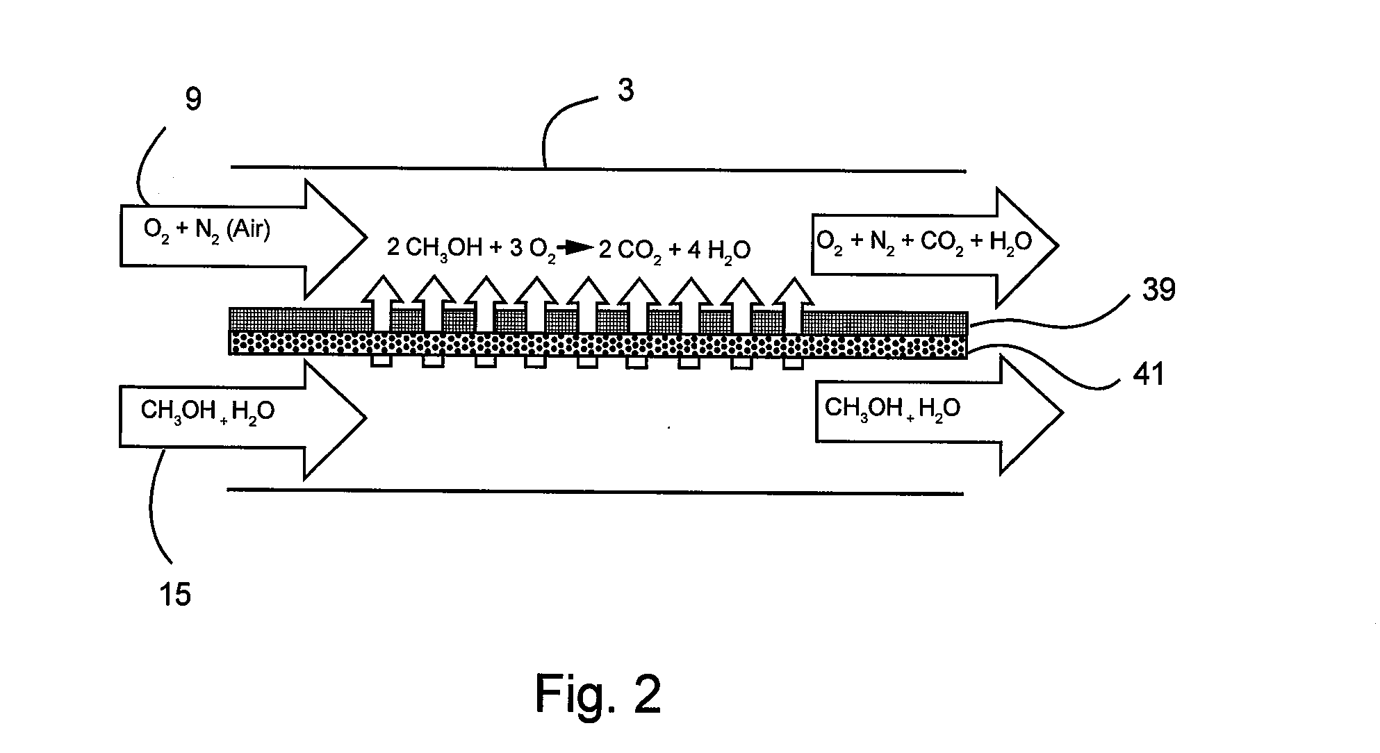
[0032]With reference to FIGS. 3 and 4, the methanol was diluted in water and the perm selective film in the catalytic carbon dioxide generator only allowed methanol molecules to pass through to the catalyst, leaving the water in the fuel stream. Since methanol and water are both a clear solution, it is not visible to the user how much methanol is left in the fuel solution. Tests were performed to investigate the speed of fuel depletion with different molarities and volumes. During the first depletion test, the fuel concentration was 1 molar methanol in distilled water. Air and fuel flow speed were kept at a constant level and CO2 production was measured every 5 minutes. After 10 minutes, the CO2 production started to drop with a linear gradient. The same test was executed with a volume of 250 mL and a 4 molar fuel concentration. At a...

example 2

[0034]With reference to FIGS. 5 and 6, theoretically, the {dot over (V)}CO2 produced by the catalytic carbon dioxide generator should be controllable by getting the air and fuel flow at a correct setpoint. When the fuel flow is lowered, less fuel molecules are fed to the catalyst, thus fewer molecules will be oxidized and less CO2 will be produced. As such, the catalytic carbon dioxide generator was run at different air and fuel flow rates. During these tests, the fuel was not recycled. The data collected in FIGS. 5 and 6 shows a difference in {dot over (V)}CO2 due to fuel flow variation. At 4 molar the fuel flow did not influence {dot over (V)}CO2. This is caused by the high concentration of methanol. Even at lower fuel speeds, there were a lot more molecules of methanol available than there were molecules of O2 present in the airstream that are needed for the oxidation of methanol.

[0035]The above discussion demonstrates that it is possible to control the flow rate or stream of CO2...


PUM


Abstract

A respiratory metabolic simulator is disclosed. The respiratory metabolic simulator includes a catalytic carbon dioxide generator having a first inlet adapted for receiving a fuel and a second inlet adapted for receiving a gas; a breathing simulator; and a controller; wherein an exhaust of the catalytic carbon dioxide generator combines with an exhaust of the breathing simulator; and wherein the controller is configured to vary at least one of the fuel and the gas provided to the catalytic carbon dioxide generator such that the combined exhausts emulate human exhalation.

Description

CROSS REFERENCE TO RELATED APPLICATIONS[0001]This application claims priority to U.S. Provisional Patent Application No. 61 / 879,478 entitled “Metabolic Simulator having a Catalytic Engine”, filed Sep. 18, 2013, which is hereby incorporated by reference in its entirety.BACKGROUND OF THE INVENTION[0002]1. Field of the Invention[0003]The invention relates generally to metabolic simulators. More specifically, the invention relates to metabolic simulators having a catalytic engine that provides catalytic combustion to a fuel in order to produce carbon dioxide.[0004]2. Description of Related Art[0005]All living organisms with lungs breathe air in order to ventilate their lungs. The human body consumes oxygen (O2) and generates carbon dioxide (CO2) in the process of metabolism. The general rule of thumb is 21% of O2 goes into the lungs and roughly 17% O2 and 4% CO2 comes out of the lungs. A breathing simulator is capable of breath by breath control of a simulated ‘patient’. As can be appre...

Claims


Application Information

Patent Timeline
IPC IPC(8): B01J7/00C01B31/20C01B32/50
CPCC01B31/20B01J7/00C01B32/50
Inventor FREMBGEN, STEFAN
Owner INGMAR MEDICAL
Why Eureka
Try Eureka