
Hot-Pluggable Uninterruptible Power Supply Module

a power supply module and uninterruptible technology, applied in the direction of emergency power supply arrangements, transportation and packaging, dc source parallel operation, etc., can solve the problems of additional external space, likely affected computer server operation, and use of usp

Active Publication Date: 2015-03-19
COMPUWARE TECH
View PDF0 Cites 8 Cited by
  • Summary
  • Abstract
  • Description
  • Claims
  • Application Information

AI Technical Summary

Benefits of technology

The present invention provides a hot-pluggable uninterruptible power supply module that can support redundancy and maintain a power uninterrupted condition in hot swapping connection with an external AC power source. The module comprises a control module and a second power supply device, which is connected to the control module and the electronic system. The second power supply device is also connected to an external AC power source. The invention ensures that the hot-pluggable uninterruptible power supply module can be quickly and easily inserted into the electronic system without interrupting power supply. The technical effects of the invention include improved reliability, reduced downtime for maintenance, and improved efficiency of power utilization.

Problems solved by technology

When the AC power source is interrupted or is of sufficiency is supplying electrical power due to certain factors and reasons, the operation of the computer server is likely affected and events of unexpected system shutdown or service interruption may consequently result.
However, using USP has disadvantages, including an additional external space required for installation of the UPS, the computer server being shut down during the installation or maintenance, and reduction of energy efficiency due to the consumption of electrical power by the UPS and voltage conversion.

Method used


Image

  • Hot-Pluggable Uninterruptible Power Supply Module
  • Hot-Pluggable Uninterruptible Power Supply Module
  • Hot-Pluggable Uninterruptible Power Supply Module

Examples


Embodiment Construction

[0024]The following descriptions are exemplary embodiments only, and are not intended to limit the scope, applicability or configuration of the invention in any way. Rather, the following description provides a convenient illustration for implementing exemplary embodiments of the invention. Various changes to the described embodiments may be made in the function and arrangement of the elements described without departing from the scope of the invention as set forth in the appended claims.

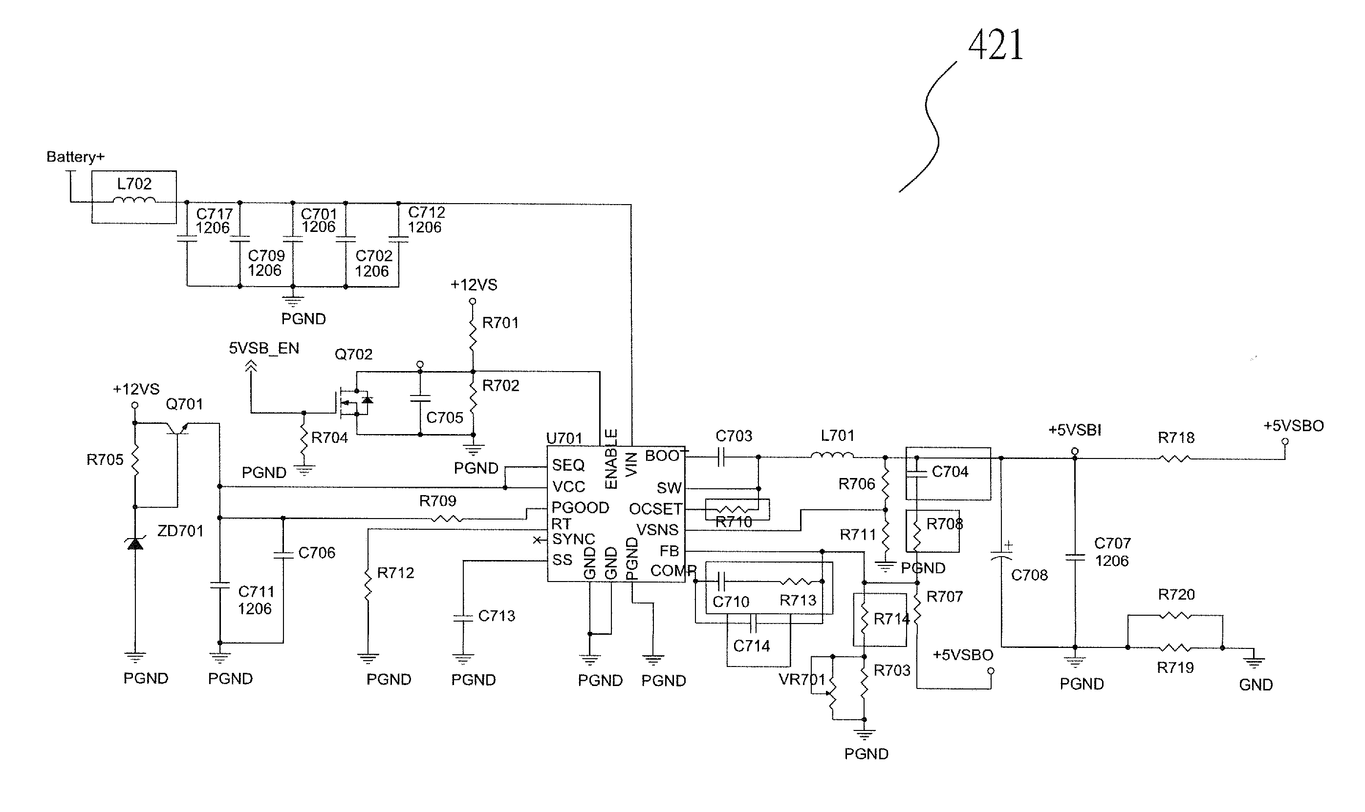
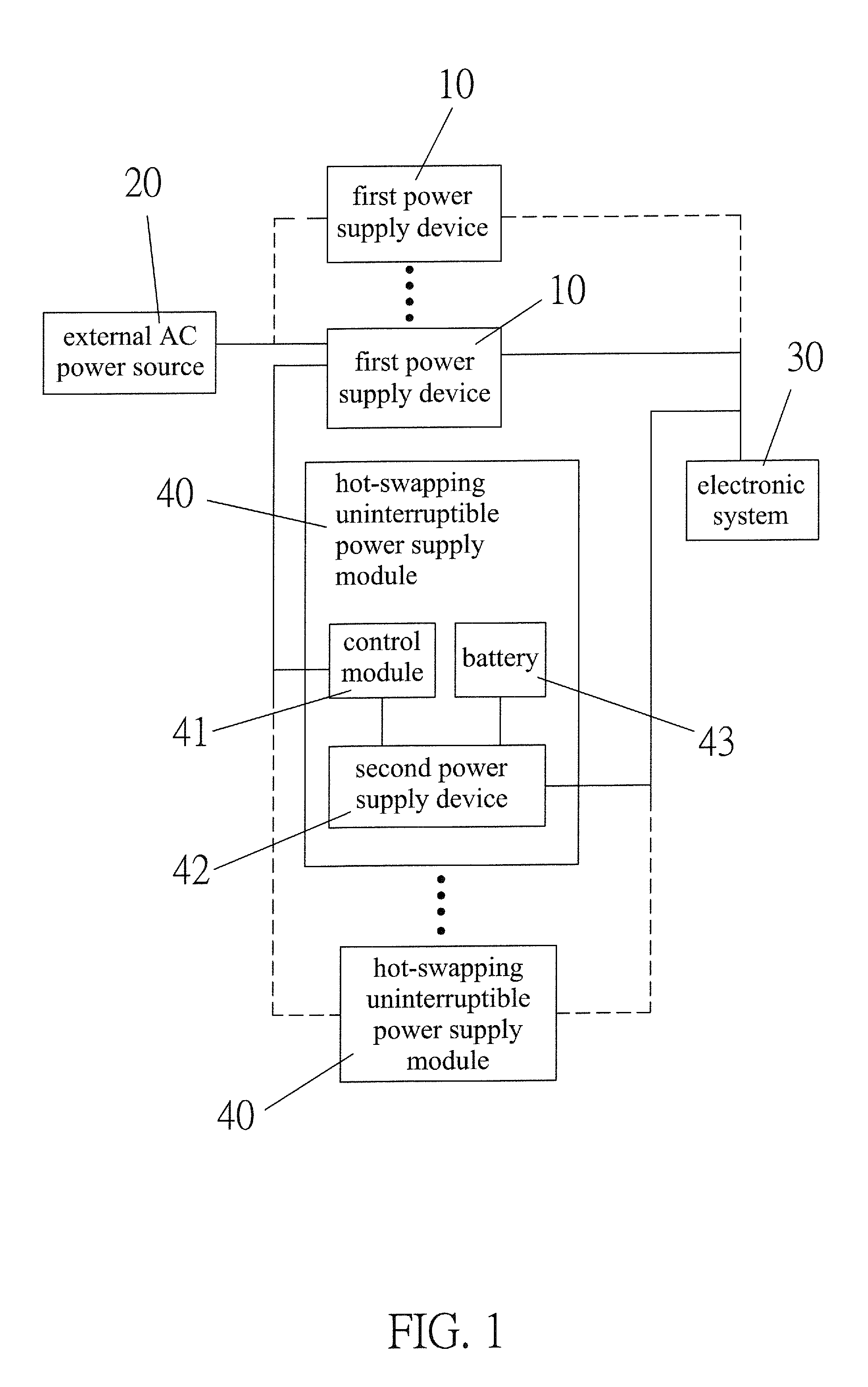
[0025]Referring to FIG. 1, the present invention provides a hot-pluggable uninterruptible power supply module, which comprises:

[0026]at least one first power supply device 10, wherein each of the first power supply devices 10 has an end electrically connected with an electronic system 30 and each of the first power supply devices 10 has another end electrically connected with an external AC power source 20, each of the first power supply devices 10 being electrically connected with each other in par...


PUM


Abstract

A hot-pluggable uninterruptible power supply module includes at least one first power supply device, each first power supply device having an end electrically connected with an electronic system and another end electrically connected with an external AC power source; at least one hot-swapping uninterruptible power supply module, each hot-swapping uninterruptible power supply module including a control module, a second power supply device, and a battery that is electrically connected with the second power supply device. The second power supply device is electrically connected with the control module. The control module of each hot-swapping uninterruptible power supply module is electrically connected with each first power supply device. The second power supply device of each hot-swapping uninterruptible power supply module is electrically connected with the electronic system and an end of each first power supply device.

Description

CROSS-REFERENCE TO RELATED APPLICATIONS[0001]This application is a continuation-in-part of U.S. patent application Ser. No. 13 / 353,332, filed Jan. 19, 2012.BACKGROUND OF THE INVENTION[0002](a) Technical Field of the Invention[0003]The present invention generally relates to a hot-pluggable uninterruptible power supply module, and more particularly to a hot-pluggable uninterruptible power supply module comprising therein a control module and a second power supply device for achieving the purpose that the hot-pluggable uninterruptible power supply module supports redundancy and maintains a system in a power uninterrupted condition in hot swapping connection with a first power supply device of an external alternate-current (AC) power source.[0004](b) Description of the Prior Art[0005]A conventional computer server receives power from an external AC power source. When the AC power source is interrupted or is of sufficiency is supplying electrical power due to certain factors and reasons,...

Claims


Application Information

Patent Timeline
Patent Type & Authority Applications(United States)
IPC IPC(8): H02J9/06H02M7/08
CPCH02J9/061H02J2009/068H02M7/08H02J1/10H02J7/04H02J9/062H02J1/001H02J7/00716H02J9/068
Inventor LIANG, CHIEN-TAHUANG, WEI-CHENG
Owner COMPUWARE TECH
Learn More