High-resolution scanning microscopy

a scanning microscopy and high-resolution technology, applied in the field of high-resolution scanning microscopy microscopy microscopes, can solve the problems of unable to reach the theoretical maximum by an error of 20%, and the pixels of the detector array can additionally be too large for the required resolution, so as to reduce and/or completely eliminate residual inaccuracy, high precision, and high resolution

Active Publication Date: 2015-03-19
CARL ZEISS MICROSCOPY GMBH
View PDF21 Cites 26 Cited by
  • Summary
  • Abstract
  • Description
  • Claims
  • Application Information

AI Technical Summary

Benefits of technology

[0036]The resolution of the diffraction structure of the single image also makes it possible to determine a direction of movement of the spot, wherein the sample is moved along the same during the scanning. This direction of movement is known in principle from the mechanism of the scanner (for example, a scanning mirror or a moving sample table), but nevertheless there are residual inaccuracies in this case arising from the mechanism. These can be eliminated by evaluating signals of individual pixels of the detector array by means of cross-correlation. In this case, one takes advantage of the fact that, relative to [sic] adjacent image pixels in the sample overlap to a certain degree due to the diffraction-limited imaging of the spot, whereas their centers lie adjacent to each other. If the signals of such image pixels are subjected to a cross-correlation, it is possible to reduce and / or to completely eliminate a residual inaccuracy which persists as a result of unavoidable tolerances of the scanning mechanism.
[0037]In addition to the increased resolution, it is possible to detect a chronological change in the fluorescence in the detection volume comprised by the spot via the spatial and chronological correlation of the signals from a series of measurements of the individual detector elements (to which the image pixels in the detection plane are functionally assigned). By way of example, diffusion coefficients can be determined from a chronological correlation, as in fluorescence correlation spectroscopy, and oriented diffusion and diffusion barriers can be visualized by incorporating the spatial correlation between image pixels. Movement processes of the fluorescence molecules are also of great interest for tracking applications as well, because the illumination spot in this case should follow the movement of the fluorescent molecules. The arrangement described here makes it possible to determine the movement direction with high precision, even during the bleaching time of a pixel. For this reason, it is preferred, as one implementation, that changes in the sample are detected by means of determining and evaluating a chronological change in the diffraction-limited single image for the point or linear spot which is stationary in the sample.
[0038]The procedure according to the invention also makes it possible to modify the illumination distribution in scanning illumination processes—for example by means of a phase filter. The method as described in Gong et al., Opt. Let., 34, 3508 (2009) can be realized very easily as a result.

Problems solved by technology

Rather, it should also encompass situations in which the configuration fails to reach theoretical maximum by an error of 20%, due to actual insufficiencies or limitations.
The pixels of the detector array can additionally be too large for the required resolution.

Method used


Image

  • High-resolution scanning microscopy
  • High-resolution scanning microscopy
  • High-resolution scanning microscopy

Examples


Embodiment Construction

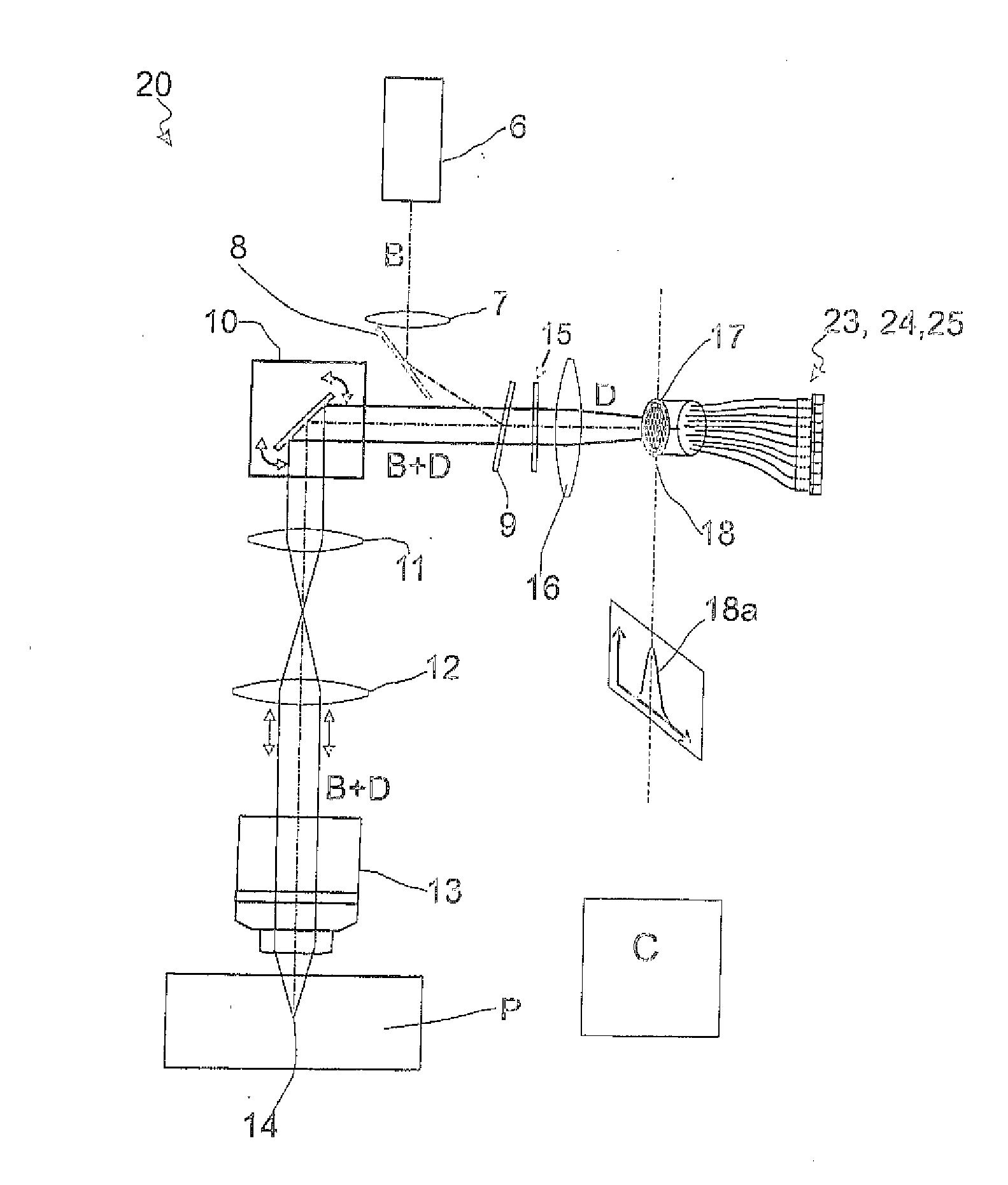
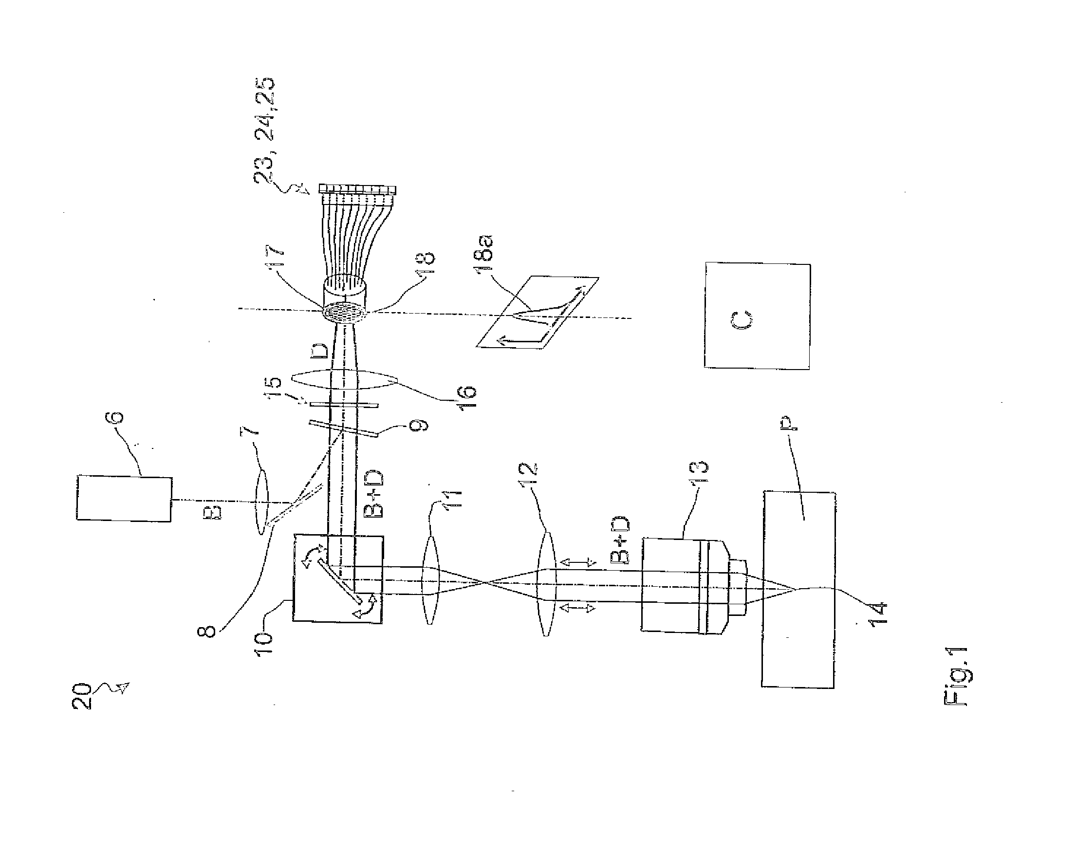
[0065]FIG. 1 schematically shows a laser scanning microscope 1 which is designed for the purpose of microscopy of a sample 2. The laser scanning microscope (abbreviated below as LSM) 1 is controlled by a control device C and comprises an illumination beam path 3 and an imaging beam path 4. The illumination beam path illuminates a spot in the sample 2, and the imaging beam path 4 images this spot, subject to the diffraction limit, for the purpose of detection. The illumination beam path 3 and the imaging beam path 4 share a plurality of elements. However, this is likewise less necessary than a scanned spot illumination of the sample 2. The same could also be illuminated in wide-field.

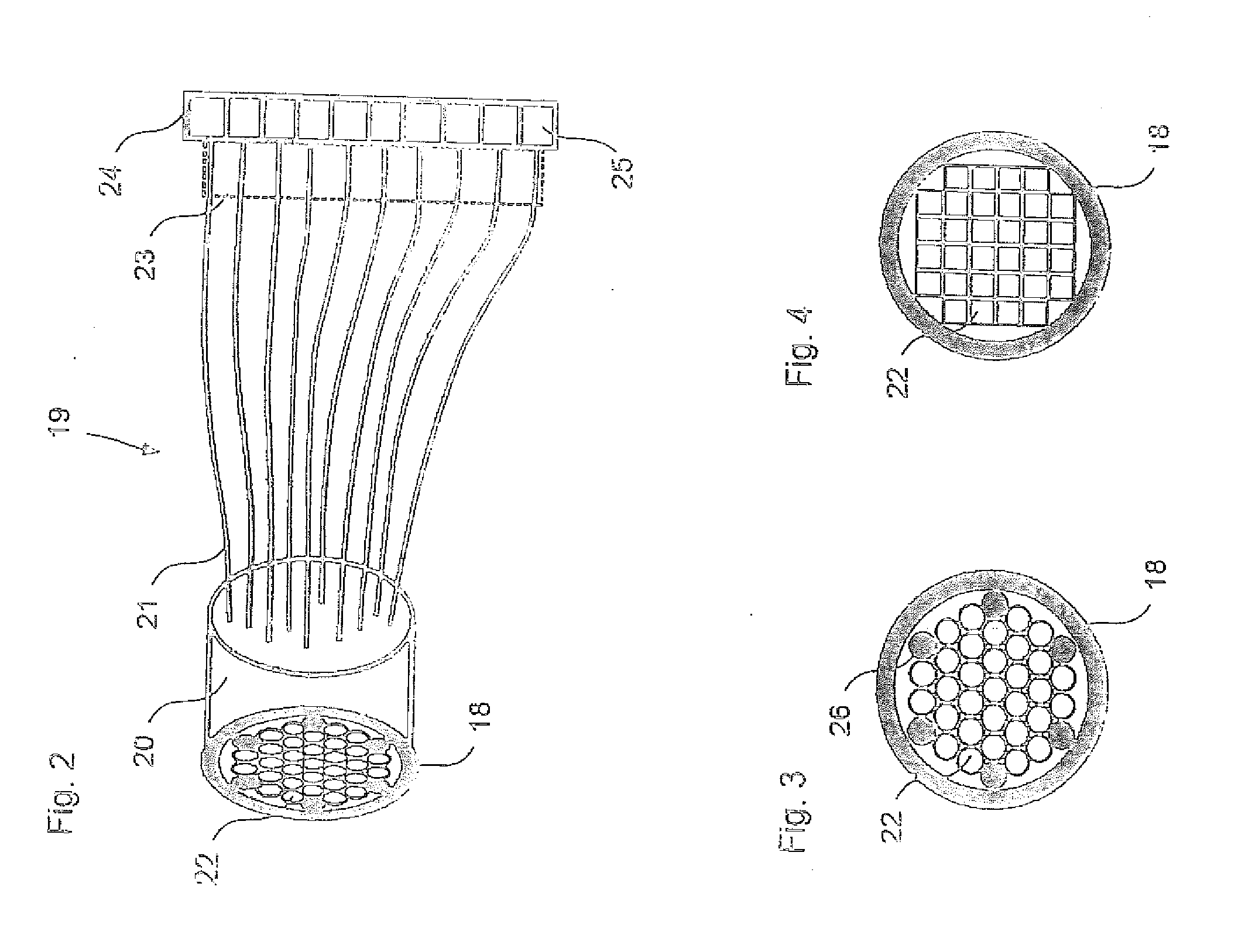
[0066]The illumination of the sample 2 in the LSM 1 is carried out by means of a laser beam 5 which is coupled into a mirror 8 via a deflection mirror 6, which is not specifically functionally necessary, and a lens 7. The mirror 8 functions so that the laser beam 5 falls on an emission filter 9 at a refl...


PUM


Abstract

A microscope and method for high resolution scanning microscopy of a sample, having: an illumination device for the purpose of illuminating the sample, an imaging device for the purpose of scanning at least one point or linear spot across the sample and of imaging the point or linear spot into a diffraction-limited, static single image below a reproduction scale in a detection plane. A detector device for detecting the single image in the detection plane for various scan positions is also provided. An evaluation device for the purpose of evaluating a diffraction structure of the single image for the scan positions is provided. The detector device has a detector array which has pixels and which is larger than the single image. At least one phase mask with a variable lateral profile of the phase influence is included in or near to the objective pupil, or in a plane which is conjugated to the objective pupil, for generating a spatial distribution of the illumination light and/or the detection light perpendicular to the optical axis, and/or in the direction of the optical axis.

Description

RELATED APPLICATIONS[0001]The present application claims priority benefit of German Application No. DE 10 2013 015 933.4 filed on Sep. 19, 2013, the contents of which are incorporated by reference in its entirety.FIELD OF THE INVENTION[0002]The invention relates to a microscope for high resolution scanning microscopy of a sample, having an illumination device for the purpose of illuminating the sample, an imaging device for the purpose of scanning a point or linear spot across the sample and of imaging the point or linear spot into a diffraction-limited, static single image, with a reproduction scale in a detection plane, a detector device for the purpose of detecting the single image in the detection plane for various scan positions, with a location accuracy which, taking into account the reproduction scale, is at least twice as high as a full width at half maximum of the diffraction-limited single image, an evaluation device for the purpose of evaluating a diffraction structure of...

Claims


Application Information

Patent Timeline
Patent Type & Authority Applications(United States)
IPC IPC(8): G02B21/00G02B21/06G02B21/16G02B21/02
CPCG02B21/0072G02B21/008G02B21/025G02B27/1013G02B21/16G02B6/06G02B26/0833G02B21/06G02B27/58G02B21/0032G02B21/0076
Inventor KLEPPE, INGONETZ, RALFKALKBRENNER, THOMASWOLLESCHENSKY, RALFNOVIKAU, YAUHENI
Owner CARL ZEISS MICROSCOPY GMBH
Why Eureka
Try Eureka