Gas turbine engine for aircraft engine

Active Publication Date: 2015-03-19
GE AVIO
View PDF21 Cites 8 Cited by
  • Summary
  • Abstract
  • Description
  • Claims
  • Application Information

AI Technical Summary

Benefits of technology

The invention aims to create a stator with features that can resolve issues in a cost-effective way.

Problems solved by technology

In time, this resulted in the construction of stators that, on the one hand, are increasingly subjected to stress, namely high fluid-dynamic loads on the blades and, on the other, have increasingly smaller thickness profiles and therefore inevitably have low rigidity, both flexural and torsional.
The reduced rigidity of the stator blade arrays has, inevitably, resulted in the construction of turbines that have been found to be unstable under certain functional conditions.
This flutter stresses the blades, leading them into structurally critical conditions, as well as generating noise emissions.
Owing to these problems, the stator blade arrays were locally reinforced or made more rigid, but at the expense of an inevitable increase in weight and, in any case, the acceptance of geometries / configurations compromised in terms of aerodynamic performance and, consequently, of efficiency.
However, the solution presented in EP-A-2075413 is not very satisfactory with regard to parts assembly, as these parts are numerous and are different from one another.
Furthermore, in EP-A-2075413, the particular type of alternation of the aerofoils along the circumferential direction is not optimal from the standpoint of flutter stabilization, as it generates significant asymmetry in the blade array.

Method used


Image

  • Gas turbine engine for aircraft engine
  • Gas turbine engine for aircraft engine
  • Gas turbine engine for aircraft engine

Examples


Embodiment Construction

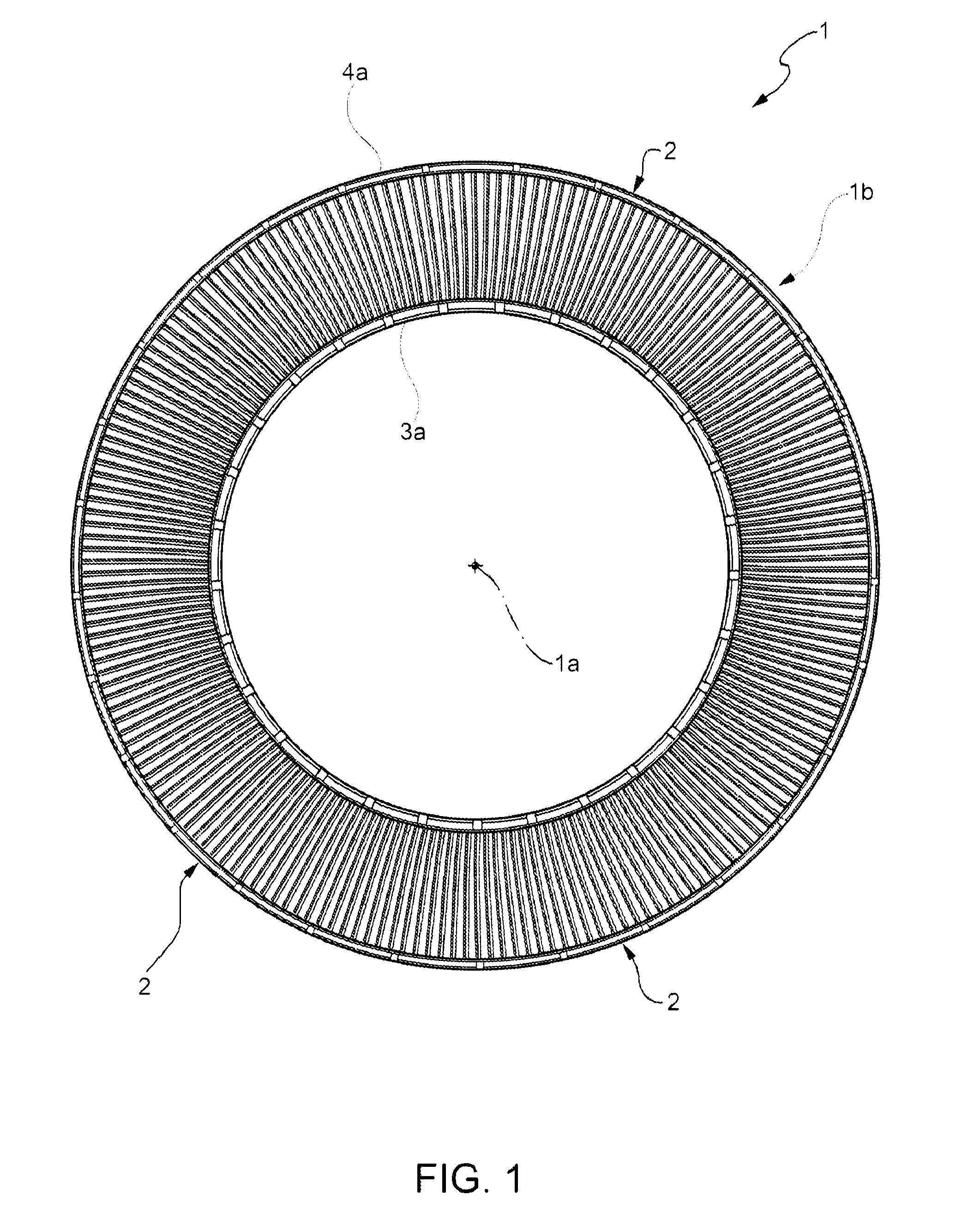
[0016]In FIG. 1, reference numeral 1 indicates, as a whole, a stator (partially shown) of a gas turbine stage (not shown) for an aircraft engine.

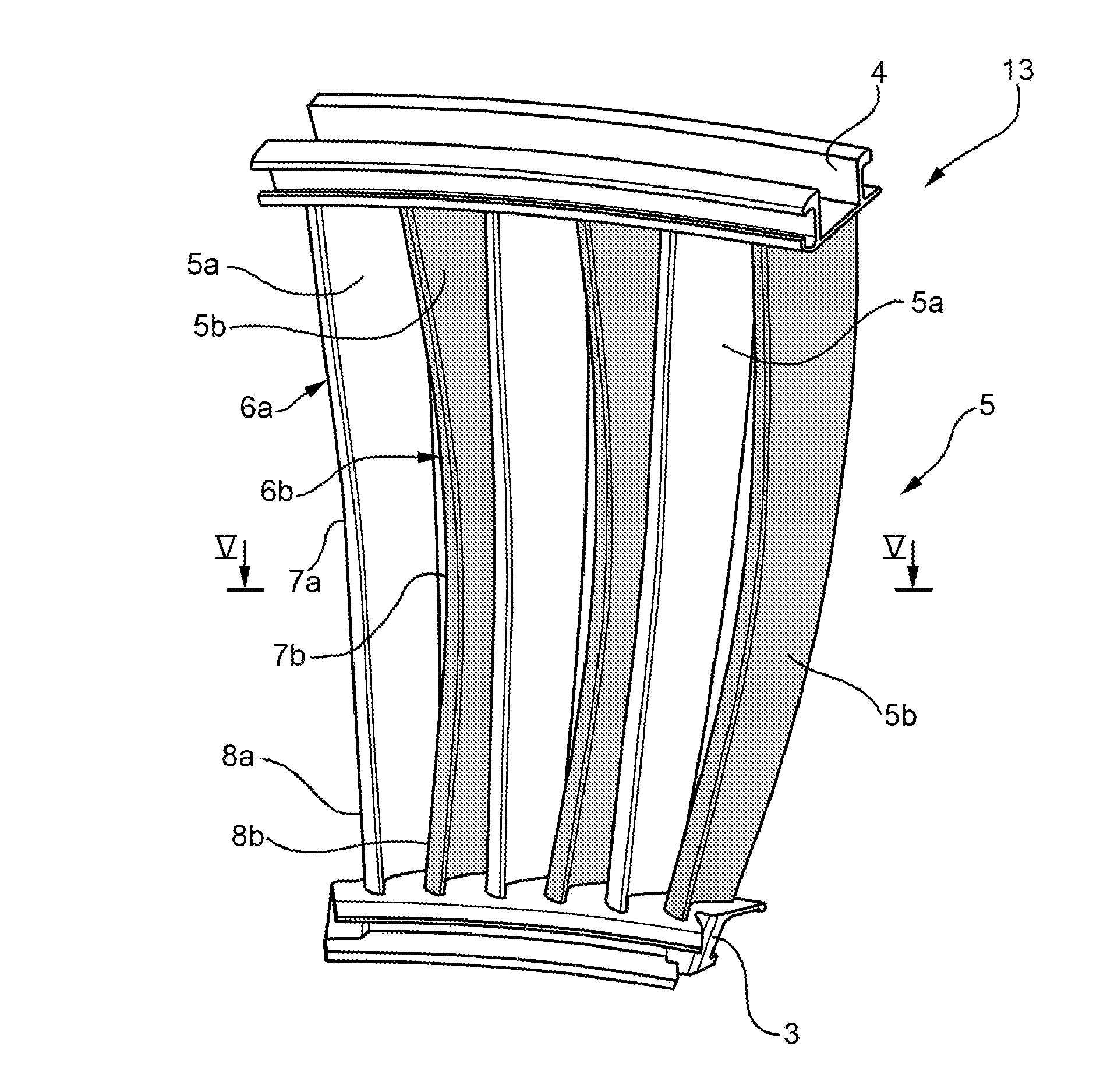
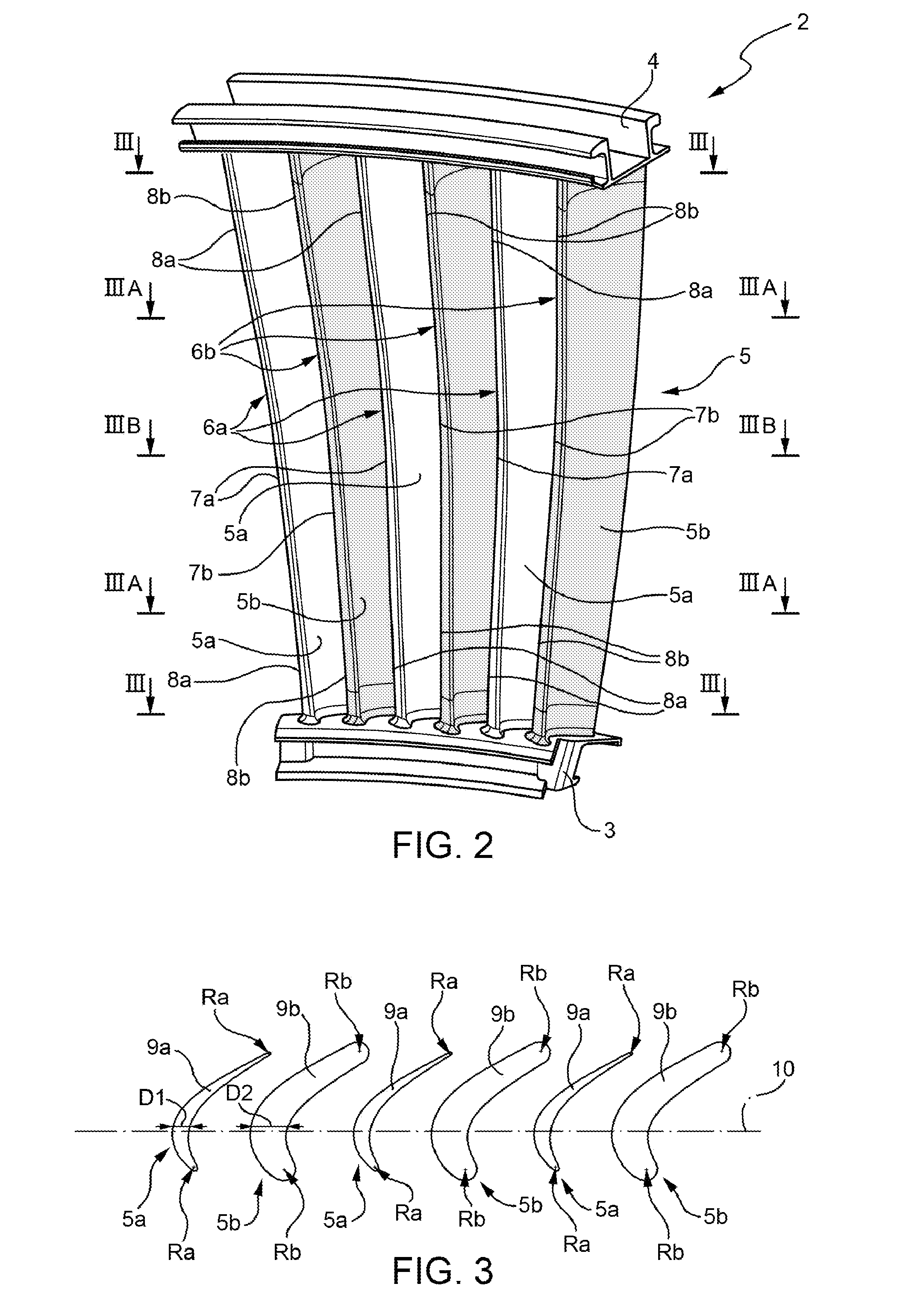
[0017]The stator 1 comprises an array or ring 1b formed by a plurality of stator blade sectors 2 arranged next to each other, coaxially to an axis 1a of the array 1b and each comprising an inner curved portion 3, an outer curved portion 4 and at least two intermediate radial blades 5 integrally connected at one end to the inner curved portion 3 and to the outer curved portion 4 at the other end, in order to form, with portions 3 and 4, a monolithic sector 2 made in one piece.

[0018]Portions 3 and portions 4 extend around the axis la like arcs of a circle and, as mentioned above, rest against and / or are connected to the portions 3 and 4, respectively, of the adjacent sectors 2 in a circumferential direction: taken together, the portions 3 thus form an inner annular end-wall 3a and the portions 4 thus form an outer annular end-wall 4a (FIG. 1)...


PUM


Abstract

A gas turbine stator for aircraft engines has a blade array with a plurality of blades constituted by a series of first blades and a series of second blades with different geometries; the array is formed by a plurality of sectors, each having an inner portion, an outer portion, at least one first blade and a least one second blade, and each defined by a body made in one piece; a single first blade is alternated with a single second blade for the entire circumference of the stator.

Description

TECHNICAL FIELD[0001]The present invention relates to a gas turbine stator for aircraft engines.BACKGROUND ART[0002]In the field of gas turbines for aircraft engines there has long been awareness of the need to increase performance by reducing weight as much as possible. In time, this resulted in the construction of stators that, on the one hand, are increasingly subjected to stress, namely high fluid-dynamic loads on the blades and, on the other, have increasingly smaller thickness profiles and therefore inevitably have low rigidity, both flexural and torsional.[0003]The reduced rigidity of the stator blade arrays has, inevitably, resulted in the construction of turbines that have been found to be unstable under certain functional conditions.[0004]It has been possible to experimentally establish that this instability was due to a marked sensitivity to aeroelastic phenomena deriving from reciprocal aerodynamic interactions between the blades of a stage with the consequent triggering...

Claims


Application Information

Patent Timeline
IPC IPC(8): F01D9/04F01D5/14
CPCF01D5/14F01D9/041F01D9/04F01D25/06F05D2260/96Y02T50/60F05D2240/12F05D2240/129
Inventor CALZA, PAOLO
Owner GE AVIO
Why Eureka
Try Eureka