
Steam turbine system with steam turbine clutch

Inactive Publication Date: 2015-03-26
GENERAL ELECTRIC CO
View PDF5 Cites 4 Cited by
  • Summary
  • Abstract
  • Description
  • Claims
  • Application Information

AI Technical Summary

Benefits of technology

The invention is a steam turbine system that includes a steam generator, a high pressure section, a low pressure section, a clutching device, and a drive shaft. The system also includes a clutching device that can be engaged or disengaged to control the operation of the system. The technical effect of the invention is to provide a flexible and efficient way to produce power using steam turbines.

Problems solved by technology

In many cases, this results in a high pressure section being engineered to also accommodate low pressure steam, and thus low temperature steam.
These configurations can alter the performance of the high pressure section, requiring changes in performance features as well as requiring moisture removal provisions within the high pressure section.
Further, the temperature changes associated with switching back and forth between a high pressure and high temperature steam to a low pressure and low temperature steam may cause thermal stress and thermal growth to components of the steam turbine.

Method used


Image

  • Steam turbine system with steam turbine clutch
  • Steam turbine system with steam turbine clutch
  • Steam turbine system with steam turbine clutch

Examples


Embodiment Construction

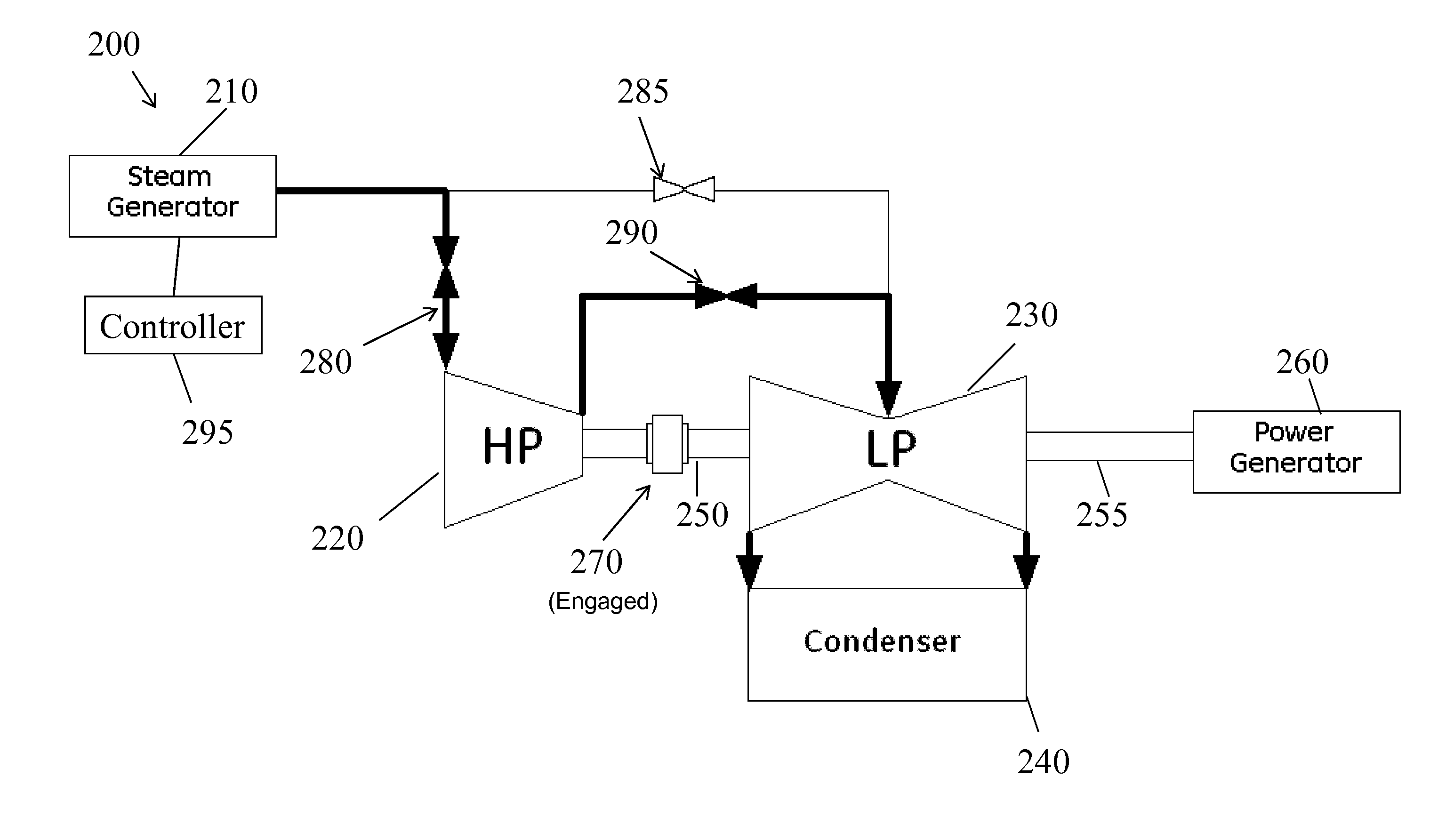
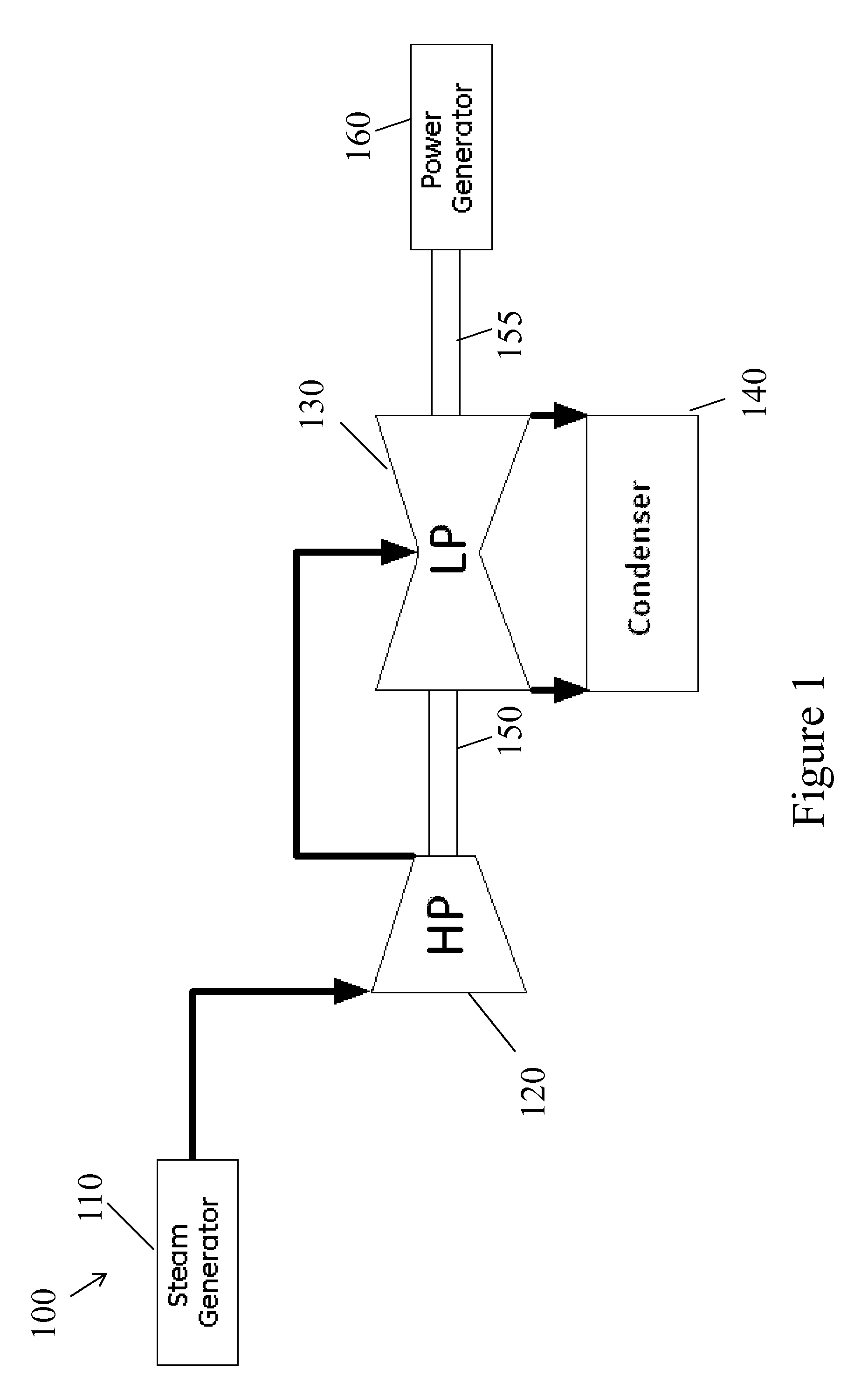
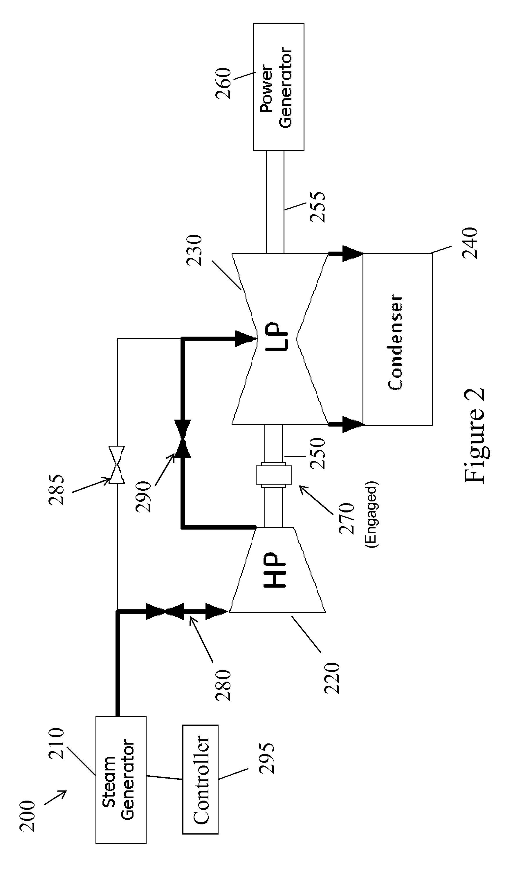
[0012]Disclosed herein is a steam turbine system including a steam turbine clutching device for disengaging a high pressure section from a power generator during low energy supply operation. Turning to FIG. 1, in the prior art, a steam generator 110 would provide steam to a high pressure section 120 of steam turbine system 100. The steam would expand within high pressure section 120 and exhaust from high pressure section 120 and would then pass to low pressure section 130. In low pressure section 130, the steam would again expand, exhausting to the condenser 140. During this operation, a first portion of a drive shaft 150 from high pressure section 120 and a second portion of the drive shaft 155 from low pressure section 130 would always provide shaft power to a power generator 160.

[0013]Still referring to FIG. 1, with both the first and second portions of the drive shafts 150 and 155 constantly supplying shaft power to power generator 160, high pressure section 120 and low pressure...


PUM


Abstract

A steam turbine system and method of operating a steam turbine system including a steam generator coupled to a high pressure section and a low pressure section. The steam turbine system may further include to a first portion of a drive shaft coupled to the high pressure section and a clutching device for releasably coupling to a power generator coupled to the first portion of the drive shaft. The steam turbine system may also include a second portion of the drive shaft for coupling to the power generator coupled to the low pressure section. The method may be implemented using a controller of the steam turbine system.

Description

FIELD OF THE INVENTION[0001]The disclosure relates generally to a steam turbine including a clutch for engaging or disengaging one or more high pressure sections from a power generator of the steam turbine, depending on a mode of operation.BACKGROUND OF THE INVENTION[0002]Many of today's steam turbines can be run in multiple modes of operation. For example, many turbines will run on high pressure steam during peak hours of operation and may switch to a low pressure steam during low energy generation. Typical steam turbines have a high pressure section and a low pressure section. However, when the turbine is run at a low pressure, the high pressure section is still utilized. In many cases, this results in a high pressure section being engineered to also accommodate low pressure steam, and thus low temperature steam. These configurations can alter the performance of the high pressure section, requiring changes in performance features as well as requiring moisture removal provisions wi...

Claims


Application Information

Patent Timeline
IPC IPC(8): F01K7/16F01K13/02
CPCF01K13/02F01K7/165F01K7/20Y02E10/46
Inventor RILEY, COLIN SCOTTRIPLEY, TAD RUSSEL
Owner GENERAL ELECTRIC CO
Learn More