Tyre layer application assembly and method

Inactive Publication Date: 2015-03-26
VMI HOLLAND BV
View PDF1 Cites 1 Cited by
  • Summary
  • Abstract
  • Description
  • Claims
  • Application Information

AI Technical Summary

Benefits of technology

The patent describes a method for accurately tracking the movement of a part of a tire layer and controlling the application of the layer to ensure even distribution. This helps to improve the performance of the tire. The method involves measuring the rotation of a tracking device attached to the tire layer and controlling the displacement of the trailing end of the layer to match the measured rotation. This ensures that the tire layer is evenly distributed around the object's circumference, even if the layer is shorter than the object's periphery.

Problems solved by technology

Such angular displacement can be caused by slipping or backlash of the tyre layer over the circumferential surface.

Method used


Image

  • Tyre layer application assembly and method
  • Tyre layer application assembly and method
  • Tyre layer application assembly and method

Examples


Embodiment Construction

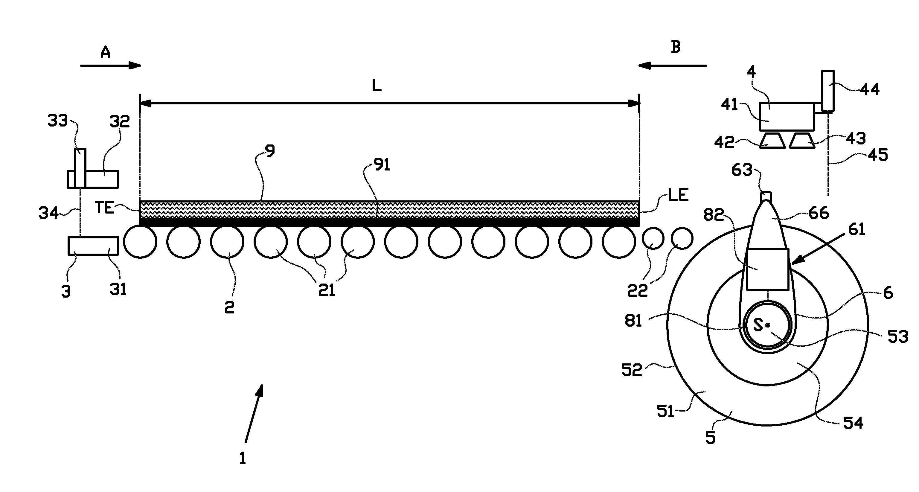
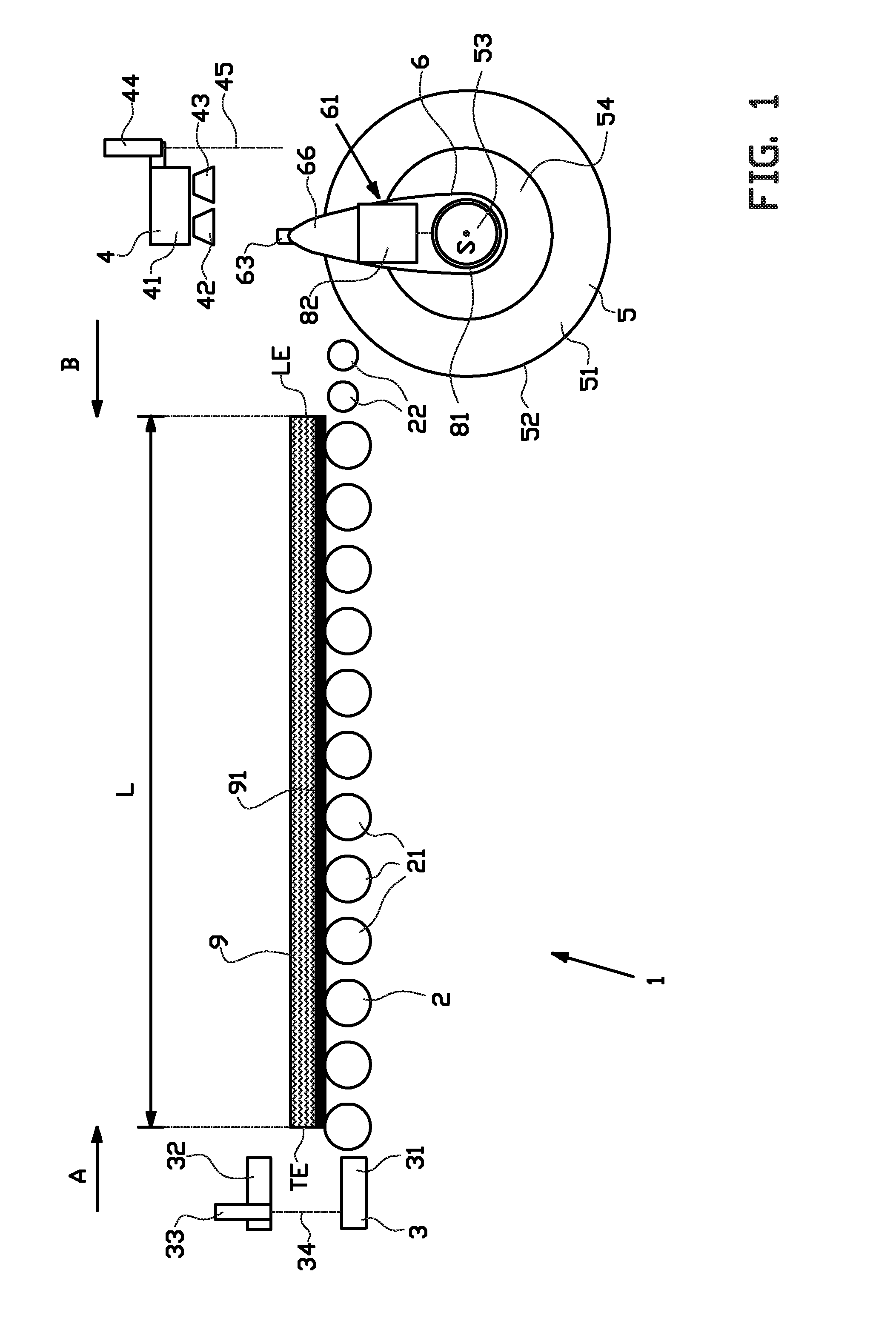
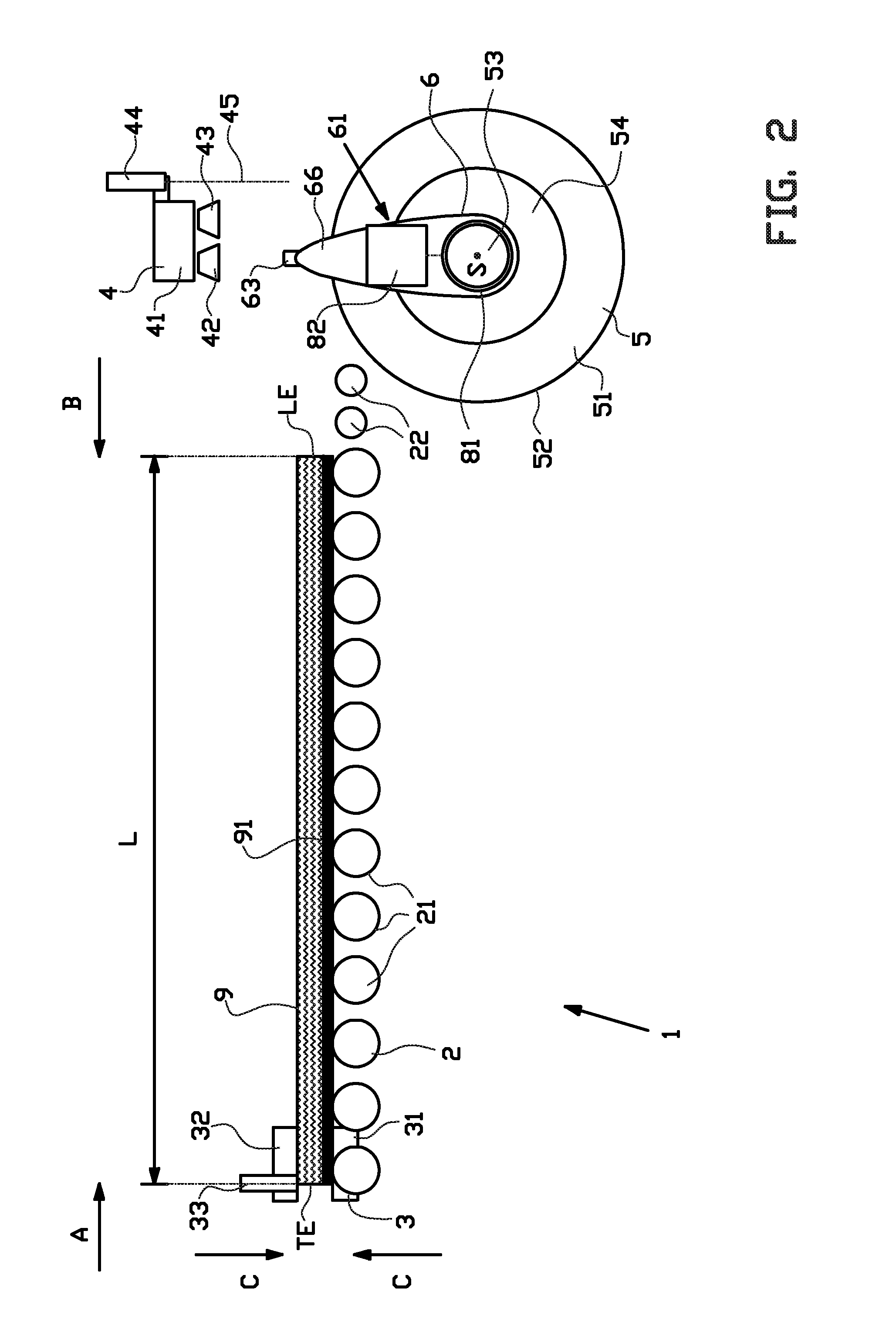
[0040]FIGS. 1-8 show a tyre layer application assembly 1 for applying a tyre layer 9 around an object 5, according to an exemplary embodiment of the invention. The tyre layer application assembly 1 comprises a conveyor 2 for supporting the tyre layer 9, and a retaining device 3 and a pulling device 4 for transporting the tyre layer 9 over the conveyor 2 towards the object 5. The tyre layer application assembly 1 is provided with a drum clamp 6 for pulling the tyre layer 9 around the object 5 in a manner which will be described hereafter.

[0041]As shown in FIGS. 1-8, the conveyor 2 of this exemplary embodiment is a roller type conveyor 2 with a plurality of rollers 21 which form a transport or support surface. At the downstream end of the conveyor 2, near the object 5, small rollers 22 are provided to provide a smooth and tangential transition from the conveyor 2 to the object 5.

[0042]The object 5 can be an empty drum or a drum with one or more other tyre layers already applied to it,...


PUM

PropertyMeasurementUnit
Lengthaaaaaaaaaa

Abstract

A tyre layer application assembly and a method for applying a tyre layer around a substantially circular circumferential surface of an object. The assembly is provided with a drive which, during application, is coupled to the object for driving the object in a driven rotation about a concentric axis of rotation with respect to the circumferential surface, wherein the assembly includes a tracking device which, during application, is arranged to be fixed to a part of the tyre layer that is applied to the circumferential surface, wherein the tracking device is rotatable in a tracking rotation about the axis of rotation of the object, independent of the driven rotation of the object about the same axis of rotation.

Description

BACKGROUND[0001]The invention relates to a tyre layer application assembly and a method for applying a tyre layer around a circumferential surface of a drum or a tyre.[0002]A method for applying a new tread around a buffed circumferential surface of an existing tyre, also known as retreading, involves the tagging of a leading end of the tread to the circumferential surface during the retreading. The circumferential surface of the tyre is subsequently rotated to wind the rest of the tread around the tyre until the trailing end meets the leading end to form a splice. Finally, the splice is stitched by a stitch roller.[0003]During winding, the tread is subjected to a pulling force to stretch the tread so that it matches the circumferential length of the circumferential surface of the tyre. The pulling force can however cause the tagged leading end of the tread to slip over the circumferential surface of the tyre. Once the leading end of the tread has slipped, its position becomes undef...

Claims


Application Information

Patent Timeline
IPC IPC(8): B29D30/16B29D30/00
CPCB29D30/16B29D2030/0038B29D2030/0033B29D30/0061B29D30/1607B29D30/3007B29D30/58B29D2030/1685B29D2030/2671B29D2030/3085B29D2030/4425B29D2030/4437
Inventor FISCHER, FLORIANJANSZEN, CORNELIS WOUTERES
Owner VMI HOLLAND BV
Why Eureka
Try Eureka