Auto-stereoscopic display device and driving method

a display device and display device technology, applied in the direction of instruments, lighting and heating apparatus, optical elements, etc., can solve the problem of practicability, and achieve the effect of reducing the effect of optical aberration

Inactive Publication Date: 2015-03-26
KONINKLIJKE PHILIPS ELECTRONICS NV
View PDF4 Cites 19 Cited by
  • Summary
  • Abstract
  • Description
  • Claims
  • Application Information

AI Technical Summary

Benefits of technology

[0016]This arrangement provides a backlight arrangement in which different parts of the backlight arrangement point in different directions. This means that different parts of the backlight arrangement will be suitable for directing images in different directions, while reducing the effect of optical aberrations resulting from large exit angles. It would in theory be beneficial to provide rotation of the lenses to have their optical axis directly towards the viewer. However, this is practically not feasible. The invention instead provides sets of lenses with different static orientations. Each tube of the light tube array directs light efficiently in its own limited angular range.

Problems solved by technology

However, this is practically not feasible.

Method used


Image

  • Auto-stereoscopic display device and driving method
  • Auto-stereoscopic display device and driving method
  • Auto-stereoscopic display device and driving method

Examples


Embodiment Construction

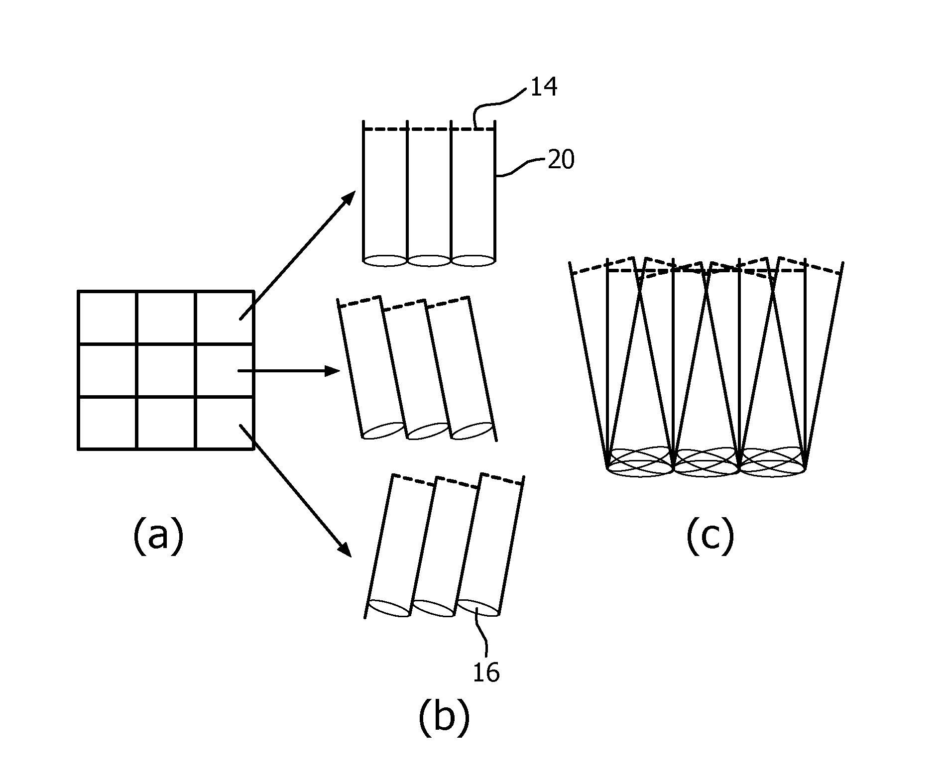
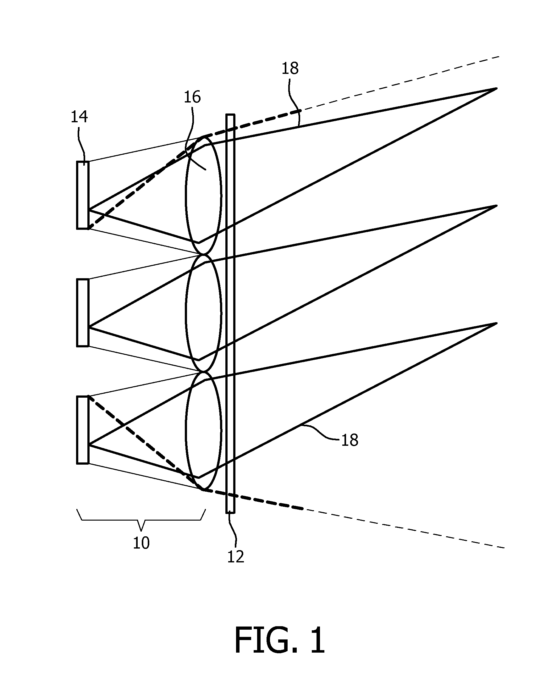
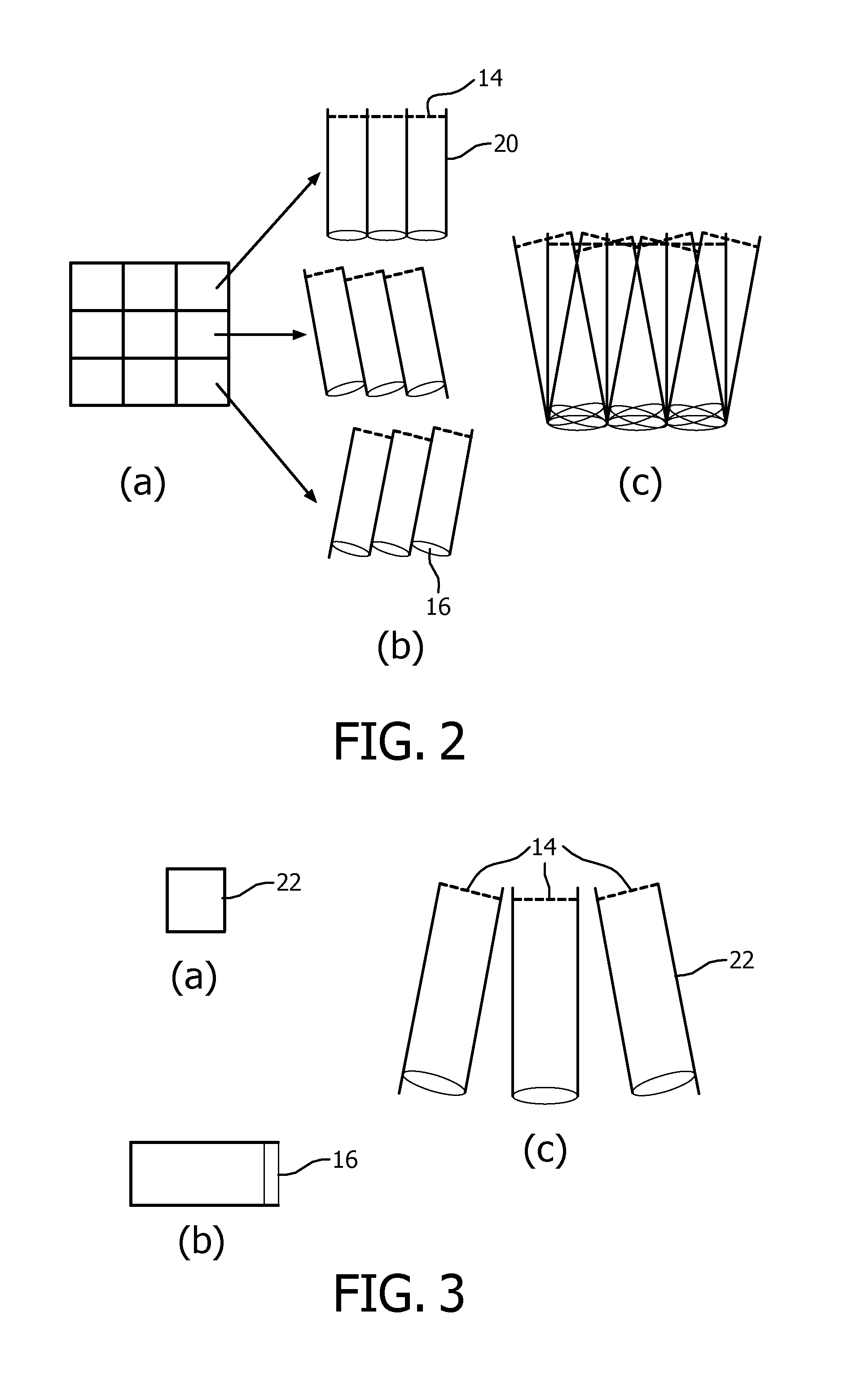
[0037]The invention provides a directional backlight arrangement for an auto-stereoscopic display in which different parts of the backlight arrangement point in different directions. This means that different parts of the backlight arrangement will be suitable for directing images in different directions, while reducing the effect of optical aberrations resulting from large exit angles.

[0038]FIG. 1 is used to explain generally the type of display device to which the invention relates.

[0039]The display comprises a backlight arrangement 10 and a light modulating display panel 12, such as an LC panel. The backlight arrangement comprises a set of segmented backlight sub-arrays 14, each of which is associated with an output lens 16.

[0040]The more backlight sub-arrays there are, the greater the number of backlight segments that can be turned on to provide illumination of the display panel, so that the intensity of the individual backlight segments can be reduced. Of course, a greater numb...


PUM


Abstract

The invention provides a directional back-light arrangement for an auto-stereoscopic display in which different parts of the backlight arrangement point in different directions. This means that different parts of the backlight arrangement will be suitable for directing images in different directions, while reducing the effect of optical aberrations resulting from large exit angles.

Description

FIELD OF THE INVENTION[0001]This invention relates to auto-stereoscopic display devices.BACKGROUND OF THE INVENTION[0002]Various types of auto-stereoscopic display device are known. Essentially, such displays include an optical arrangement which directs different views into different directions at which the eyes of a user may be located, so that the user does not need to wear special glasses for this purpose.[0003]The different directions of the views to different locations can for example be achieved with a lens arrangement, with individual lenses covering groups of pixels. The lenses then direct light from different pixels in different directions, and in this way different images (e.g. left and right) can be sent to different directions.[0004]Another approach is to use a barrier arrangement. This again has the function of limiting the direction in which light from individual pixels can be sent.[0005]A problem with this arrangement is that the resolution of the individual views is ...

Claims


Application Information

Patent Timeline
Patent Type & Authority Applications(United States)
IPC IPC(8): H04N13/04G02B27/22F21V5/00G02B30/33
CPCH04N13/0418F21V5/007H04N13/0447G02B27/2214H04N13/0404G02B27/225H04N13/305H04N13/32H04N13/351H04N13/376G02B30/33G02B30/00G02B30/27
Inventor VAREKAMP, CHRISTIAAN
Owner KONINKLIJKE PHILIPS ELECTRONICS NV
Why Eureka
Try Eureka