
Method of manufacturing a component and thermal management process

a manufacturing method and component technology, applied in the direction of superimposed coating process, machine/engine, turbine, etc., can solve the problems of inadvertent filling of cooling channels, difficult and time-consuming manufacturing cooling channels in components, and complex molds that are often difficult to position relatively

Inactive Publication Date: 2015-03-26
GENERAL ELECTRIC CO
View PDF13 Cites 37 Cited by
  • Summary
  • Abstract
  • Description
  • Claims
  • Application Information

AI Technical Summary

Benefits of technology

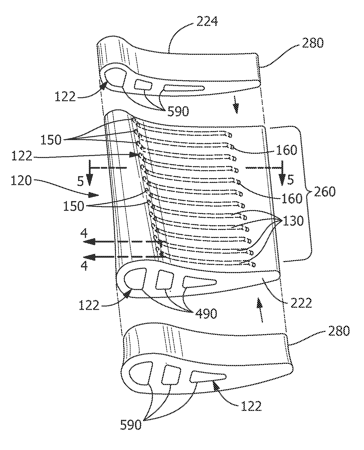
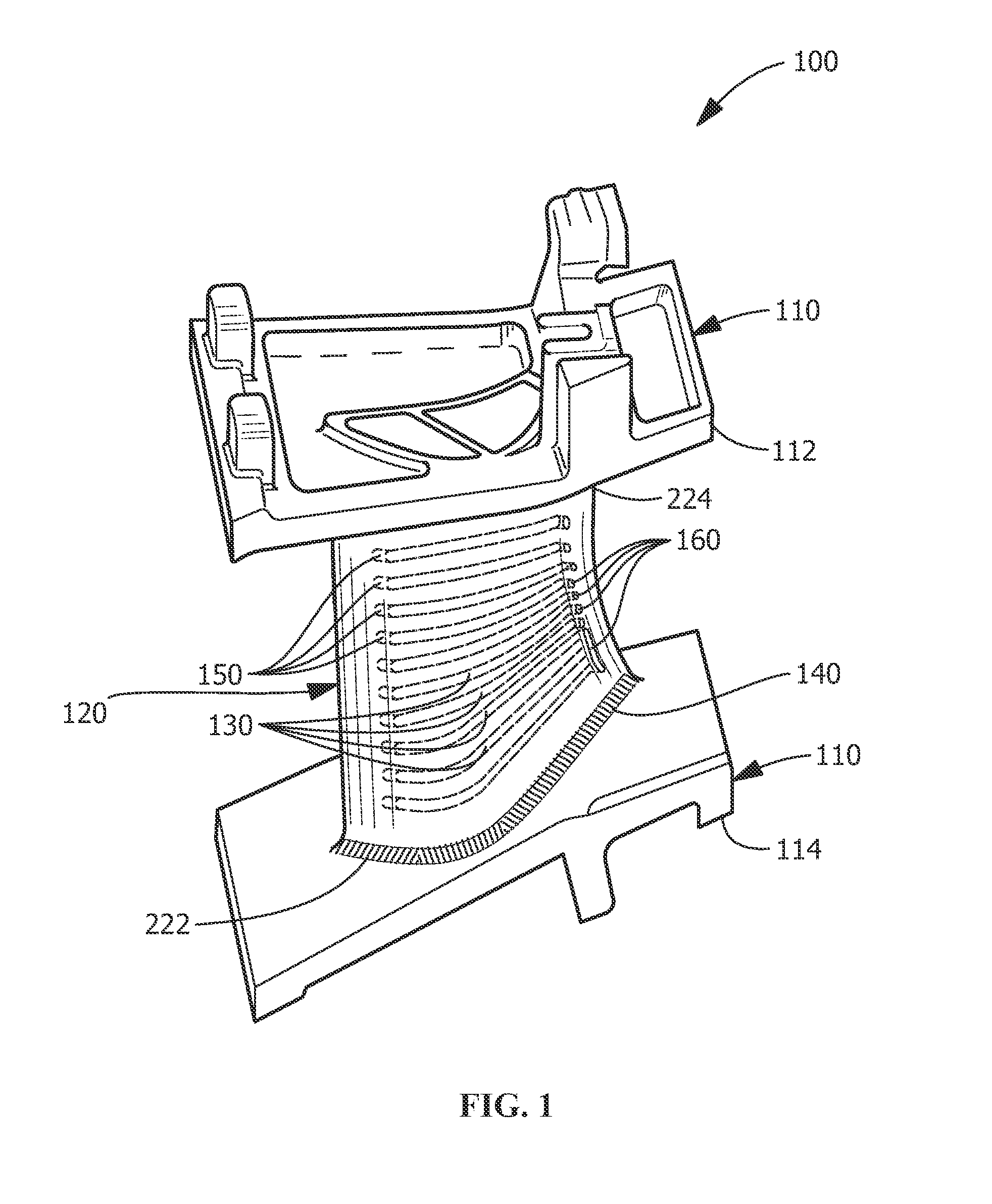
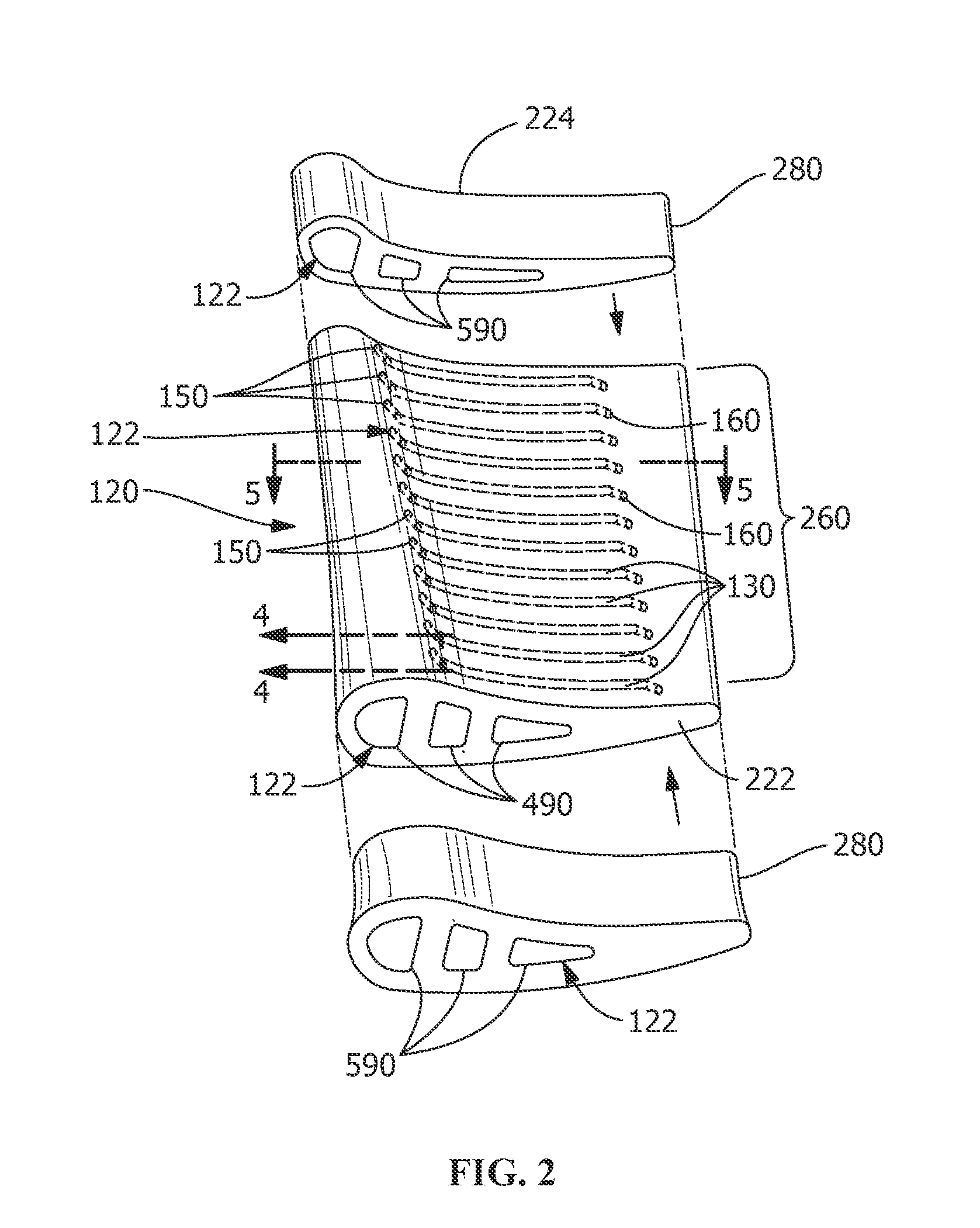
The present patent is about a method of cooling a component using a fluid pathway within a printed cooling member. The cooling member is attached to at least one portion of the component and includes one or more cooling channels near the surface of the component. The printing allows for precise placement of the cooling channels, and the fluid is transported through the cooling channels to cool the component effectively. The technical effect is improved thermal management of components, reducing surface temperature and improving overall performance.

Problems solved by technology

Manufacturing cooling channels in components can be difficult and time-consuming.
The complex molds are often difficult to position relative to the component surface near the hot gas path where cooling is required.
Closing the cooling channels can often inadvertently fill the cooling channels blocking the flow of cooling fluids, such as air from a compressor section of a gas turbine.
However, components printed by selective laser melting do not have the same temperature capability as cast high temperature superalloy materials.
Thus, use in high temperature environments has been perceived as ill-advised.

Method used


Image

  • Method of manufacturing a component and thermal management process
  • Method of manufacturing a component and thermal management process
  • Method of manufacturing a component and thermal management process

Examples


Embodiment Construction

[0017]Provided is a manufacturing process and a thermal management process using the manufactured component. Embodiments of the present disclosure, in comparison to processes and articles that do not include one or more of the features disclosed herein, provide additional cooling and heating, permit cooling in new regions, permit cooling with new materials, permit cooler and / or hotter streams to be directed from flow within turbine components, permit the useful life of turbine components to be extended, permit turbine systems using embodiments of the turbine components to be more efficient, permit turbine components to be manufactured more easily, permit manufacturing of cooling features that previously could not be made, permit manufacturing of components that otherwise cannot be made using traditional manufacturing processes, permit hybrid material construction of turbine components or a combination thereof.

[0018]One or more specific embodiments of the present invention will be de...


PUM

PropertyMeasurementUnit
Lengthaaaaaaaaaa
Lengthaaaaaaaaaa
Lengthaaaaaaaaaa

Abstract

A method of manufacturing a component and a method of thermal management are provided. The methods include forming at least one portion of the component, printing a cooling member of the component and attaching the at least one portion to the cooling member of the component. The cooling member includes at least one cooling feature. The at least one cooling feature includes at least one cooling channel adjacent to a surface of the component, wherein printing allows for near-net shape geometry of the cooling member with the at least one cooling channel being located within a range of about 127 (0.005 inches) to about 762 micrometers (0.030 inches) from the surface of the component. The method of thermal management also includes transporting a fluid through at least one fluid pathway defined by the at least one cooling channel within the component to cool the component.

Description

FIELD OF THE INVENTION[0001]The present invention is directed to processes of manufacturing and thermal management processes using the manufactured component. More specifically, the present invention is directed to manufacturing processes for forming components that include cooling features formed therein.BACKGROUND OF THE INVENTION[0002]Turbine systems are continuously being modified to increase efficiency and decrease cost. One method for increasing the efficiency of a turbine system includes increasing the operating temperature of the turbine system. To increase the temperature, the turbine system must be constructed of materials able to withstand elevated temperatures during continued use.[0003]In addition to modifying component materials and coatings, one common method of increasing temperature capability of a turbine component includes the use of cooling channels. The cooling channels are often incorporated into metals and alloys used in high temperature regions of gas turbine...

Claims


Application Information

Patent Timeline
IPC IPC(8): F01D5/18B22F3/10B22F5/04B22F3/02
CPCF01D5/18B22F5/04B22F3/10B22F3/02B22F5/10B22F7/062B22F7/08F01D5/187B22F2999/00B22F2998/10F05D2230/30F05D2260/22141F05D2260/204B22F10/00B22F10/32B22F10/28B22F10/38B22F10/64B22D25/00B23K1/00B22F3/15B22F2003/248C23C28/00B22F2005/005B33Y80/00B33Y10/00Y02P10/25
Inventor KOTTILINGAM, SRIKANTH CHANDRUDULACY, BENJAMIN PAULMIRANDA, CARLOS MIGUELSCHICK, DAVID EDWARD
Owner GENERAL ELECTRIC CO
Learn More