Object information acquiring apparatus and method for controlling same

a technology of object information and acquisition apparatus, which is applied in the field of object information acquisition apparatus and a control method, can solve the problems that image data derived from both ultrasound echo and photoacoustic wave cannot be recognized until

Inactive Publication Date: 2015-03-26
CANON KK
View PDF7 Cites 4 Cited by
  • Summary
  • Abstract
  • Description
  • Claims
  • Application Information

AI Technical Summary

Benefits of technology

[0031]According to the present invention, in the apparatus which generates the image data of the target region in the object using the photoacoustic wave and the ultrasound echo, the image data can be recognized without waiting for the completion of scanning of the entire target region using the probe.

Problems solved by technology

However, when three-dimensional image data is generated through mechanical scanning using an integrated probe including two types of receiving functions as in Japanese Patent Application Laid-open No. 2010-269046, image data derived from both of an ultrasound echo and a photoacoustic wave cannot be recognized until full scanning with the probe is completed.

Method used


Image

  • Object information acquiring apparatus and method for controlling same
  • Object information acquiring apparatus and method for controlling same
  • Object information acquiring apparatus and method for controlling same

Examples


embodiment 1

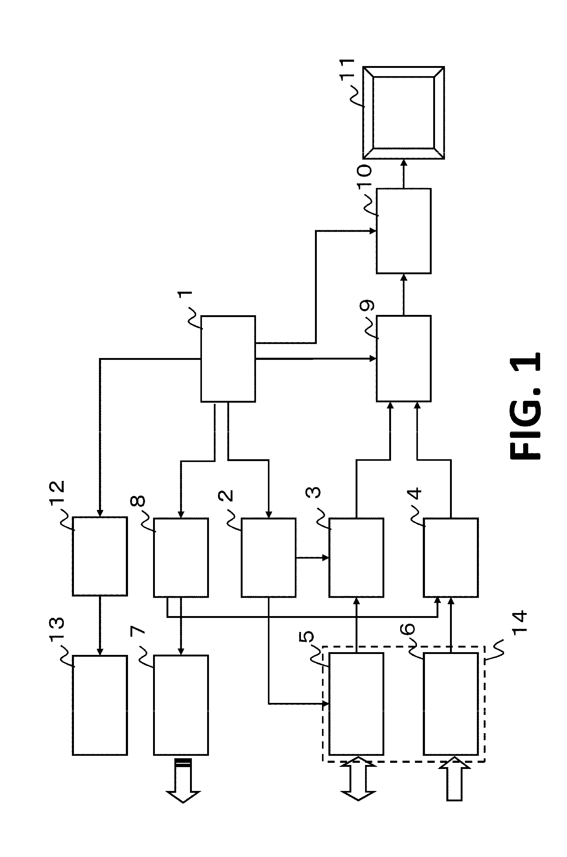
[0062]FIG. 1 is an overall configurational view of an object information acquiring apparatus most clearly representing the characteristic feature of the present invention. When an object is a living body, the apparatus may also be referred to as a living-body-information imaging apparatus.

[0063](Apparatus Configuration and Operation)

[0064]A CPU 1 is responsible for the main control of the apparatus. An ultrasound wave transmission unit 2 drives an ultrasound probe to transmit an ultrasound beam. An ultrasound wave reception unit 3 retrieves the reception signal detected by the ultrasound probe to form a beam. A photoacoustic wave reception unit 4 retrieves the reception signal detected by a photoacoustic probe.

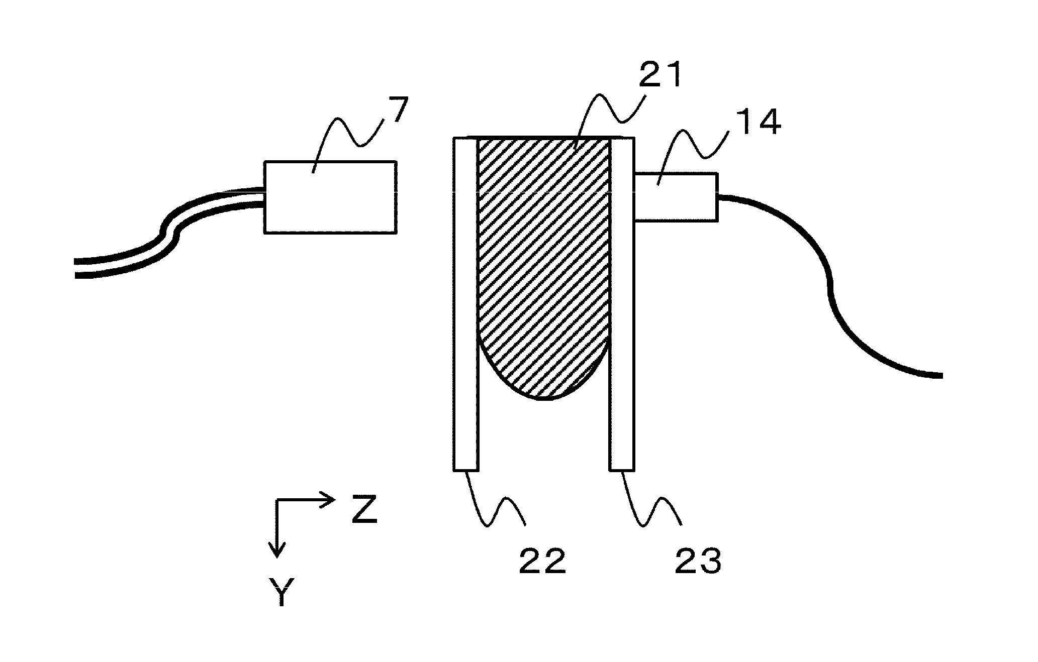
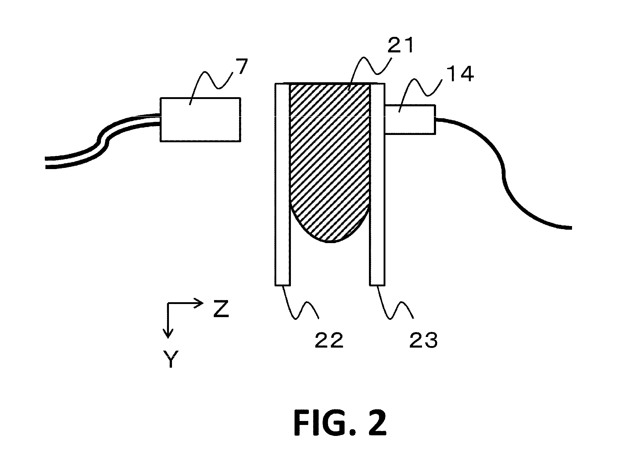
[0065]A 1D array of probes 5 generate an ultrasound wave and detects a reflection echo. A 2D array of probes 6 are used to detect the signal of a photoacoustic wave. A probe 14 is an integrated mechanism including the ultrasound probes 5 and the photoacoustic probes 6.

[0066]A ...

embodiment 2

[0098]In the present embodiment, a method of applying the present invention to an object information acquiring apparatus which sets a region of interest (ROI) in an object and the effect thereof will be described. The apparatus of the present embodiment has an input unit which receives a designation input from the user and sets the ROI in the surface of the target.

[0099]When the image data of the object 21 is acquired on the basis of the PAT, it is preferable to preliminarily estimate the X- and Y-positions of the lesion 71 from the result of diagnosis using another modality (MRI, X-ray mammography, or an ultrasound wave), set the periphery of the lesion as the ROI, and perform measurement. By setting the ROI, it is possible to reduce a measurement time when there is no need to measure the entire object and generate detailed image data aimed at only a required region.

[0100]FIGS. 8A and 8B show the images displayed on the display in the present embodiment. FIG. 8A is a camera image f...


PUM


Abstract

An object information acquiring apparatus of the present invention includes a receiver that receives an ultrasound echo and a photoacoustic wave, a scanner of the receiver, a processor that generates structural distribution information and functional distribution information, and a controller that causes a display to display each of the distribution information items. The controller causes, during the period in which the receiver receives the photoacoustic wave from a partial region formed of at least a part of the object and in which the processor generates the functional distribution information on the partial region, the display to sequentially display the structural distribution information generated by the processor on the basis of the ultrasound wave reflected from the partial region as the scanner moves the receiver to implement scanning.

Description

BACKGROUND OF THE INVENTION[0001]1. Field of the Invention[0002]The present invention relates to an object information acquiring apparatus and a method for controlling the same.[0003]2. Description of the Related Art[0004]Conventionally, in an ultrasound diagnostic apparatus used for medical image diagnosis, a probe including a vibrating element having the function of transmitting / receiving an ultrasound wave has been used. When an ultrasound beam formed by synthesizing ultrasound waves is transmitted from the probe toward an object, the ultrasound beam is reflected by a region (i.e., the boundary between tissues) in the object where an acoustic impedance changes. Through the reception of the refection echo thereof by the probe and the image reconstruction by an information processor on the basis of the intensity thereof, two-dimensional image data (tomographic slice image) showing the structural distribution information of living tissues can be acquired.[0005]According to the techn...

Claims


Application Information

Patent Timeline
Patent Type & Authority Applications(United States)
IPC IPC(8): A61B8/08A61B5/00A61B8/00
CPCA61B8/5207A61B5/0095A61B8/461A61B8/08A61B8/0825A61B8/4416A61B8/4461A61B8/469G01S7/52063G01S15/8915G01S15/8925G01S15/8938G01S15/8993G01S15/8997A61B8/483
Inventor TATEYAMA, JIRO
Owner CANON KK
Why Eureka
Try Eureka