Centrifugal spark arrestor assembly

a centrifugal spark and assembly technology, applied in the field of centrifugal spark arrestors, can solve problems such as the operation of sparks

Inactive Publication Date: 2015-04-02
ROBOVENT PROD GRP
View PDF25 Cites 3 Cited by
  • Summary
  • Abstract
  • Description
  • Claims
  • Application Information

AI Technical Summary

Benefits of technology

[0011]The present invention solves the problem of particulate accumulating on spark arresting screens, which requir...

Problems solved by technology

All of these opera...

Method used


Image

  • Centrifugal spark arrestor assembly
  • Centrifugal spark arrestor assembly
  • Centrifugal spark arrestor assembly

Examples


first embodiment

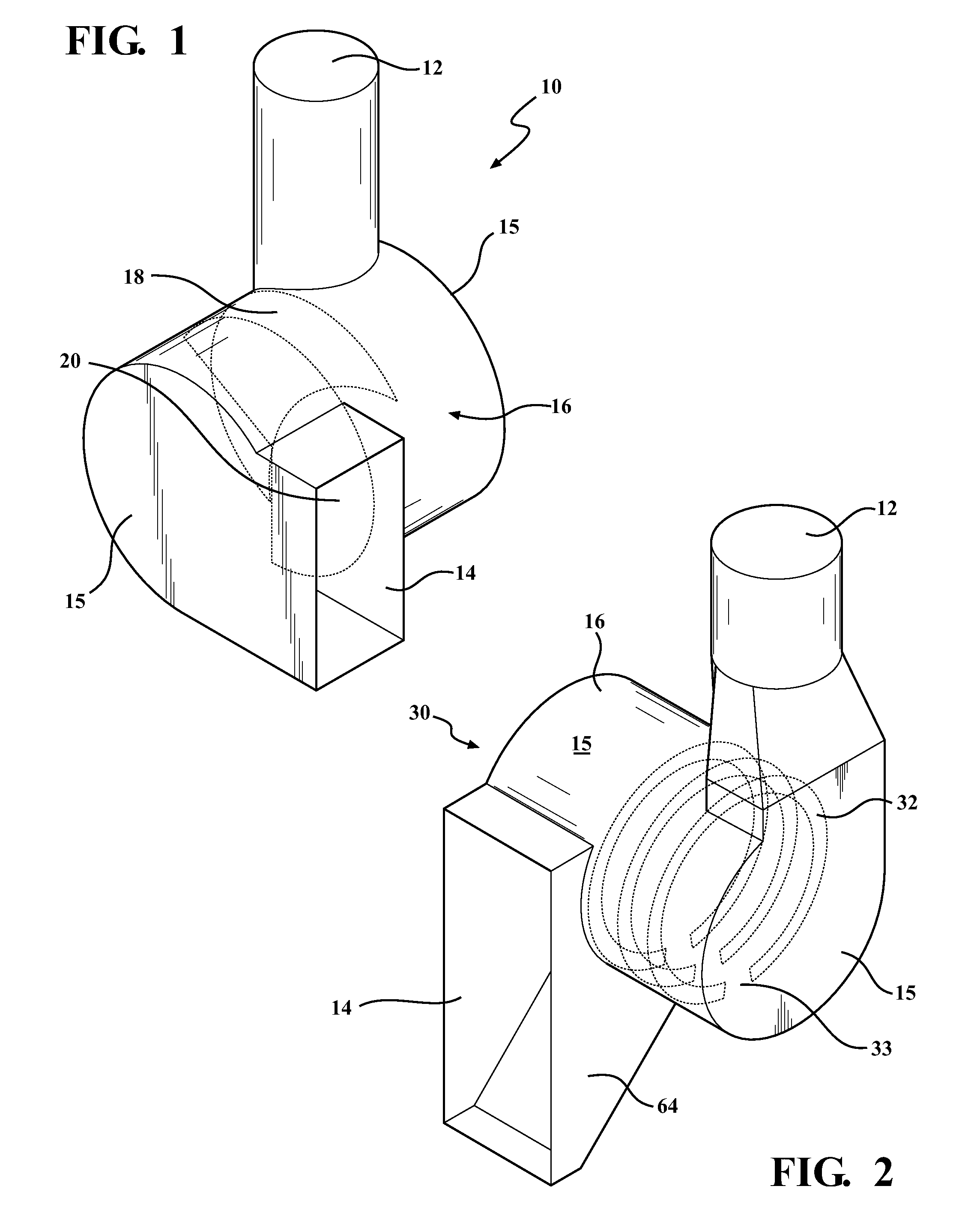
[0032]the centrifugal spark arrestor assembly of the present invention is shown generally at 10 in FIG. 1. The centrifugal spark arrestor assembly 10 has an inlet 12, an outlet 14 and a main body 16. In use, the inlet 12 is operatively connected to an area such as a workstation, which can be for example a welding station. The workstation is not illustrated but will be known to anyone of ordinary skill in the art. The operative connection can include any typical connection, such as for example, a tubular conduit that extends adjacent to the work area and connects directly to the inlet 12. The outlet 14 is operatively connected to an industrial air-filtering unit. The applicant of the present invention is a manufacturer of industrial air-filtering units. As will be understood by those of ordinary skill in the art, depending upon the application, various industrial air-filtering units could be used in connection with the spark arrestor assembly of the present invention. Furthermore, as...

second embodiment

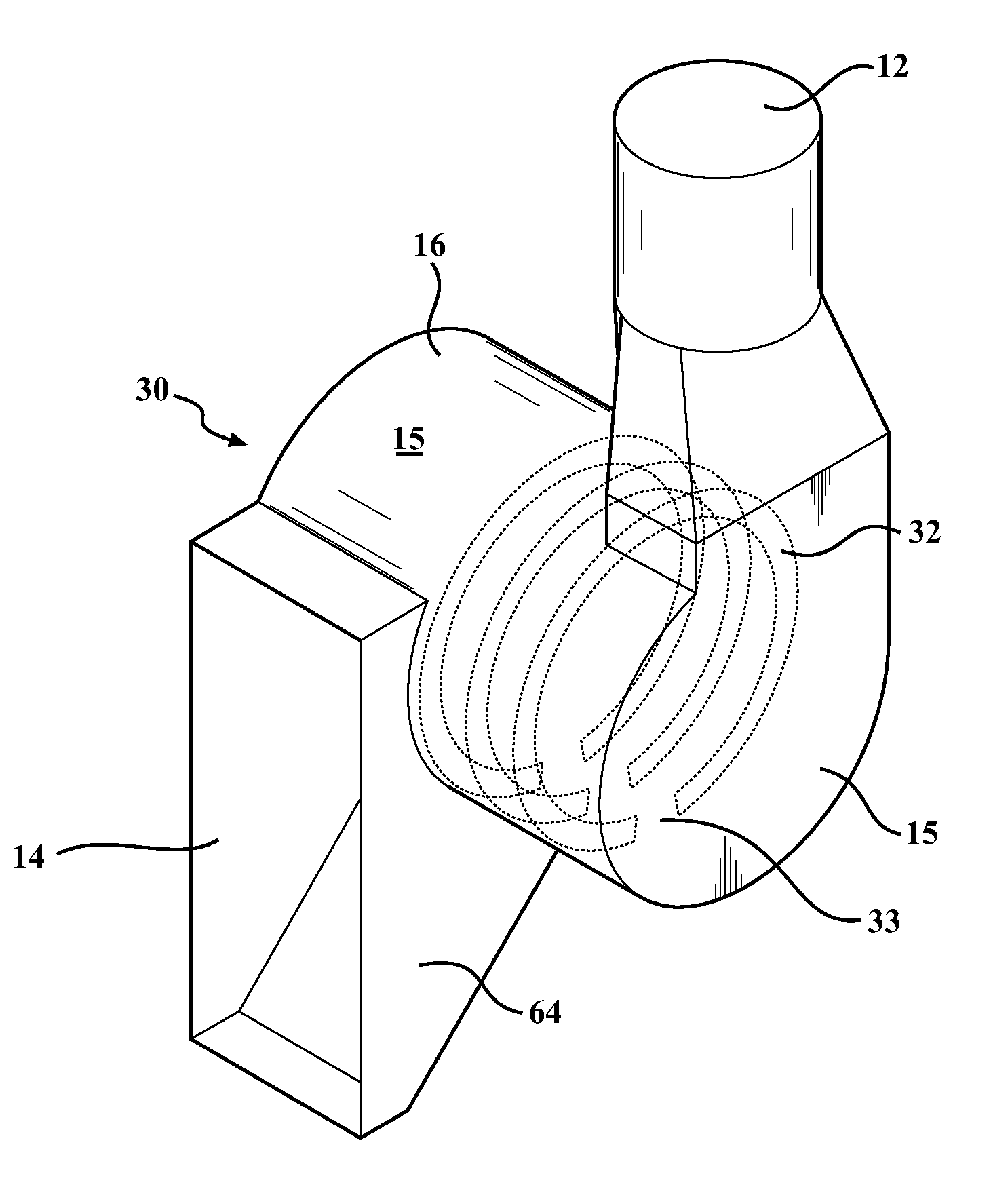
[0036]With reference to FIG. 2, the centrifugal spark arrestor of the present invention is illustrated at 30. In this embodiment, as in the last embodiment, there is an inlet 12, and outlet 14 and a main body 16 closed at both ends 15. In the centrifugal spark arrestor assembly 30, the baffles 32 are 3 a series of spaced open rings. In this embodiment, the air is pulled into the inlet 12 generally perpendicular to the longitudinal axis of the main body 16 to create a centrifugal flow through the body 16. Material entrained in the air-flow impinges upon the inner wall of the body 16 as well as along the surfaces of the rings 32. As the material flows across the individual rings 32, it exits each individual ring 32 at the opening or exit 33 to engage the adjoining ring 32. Due to the centrifugal force of the air, the entrained particles are forced to engage and slide along the spaced rings 32 extending outwardly from the inner wall of the body 16. In this embodiment, there is a plenum...

third embodiment

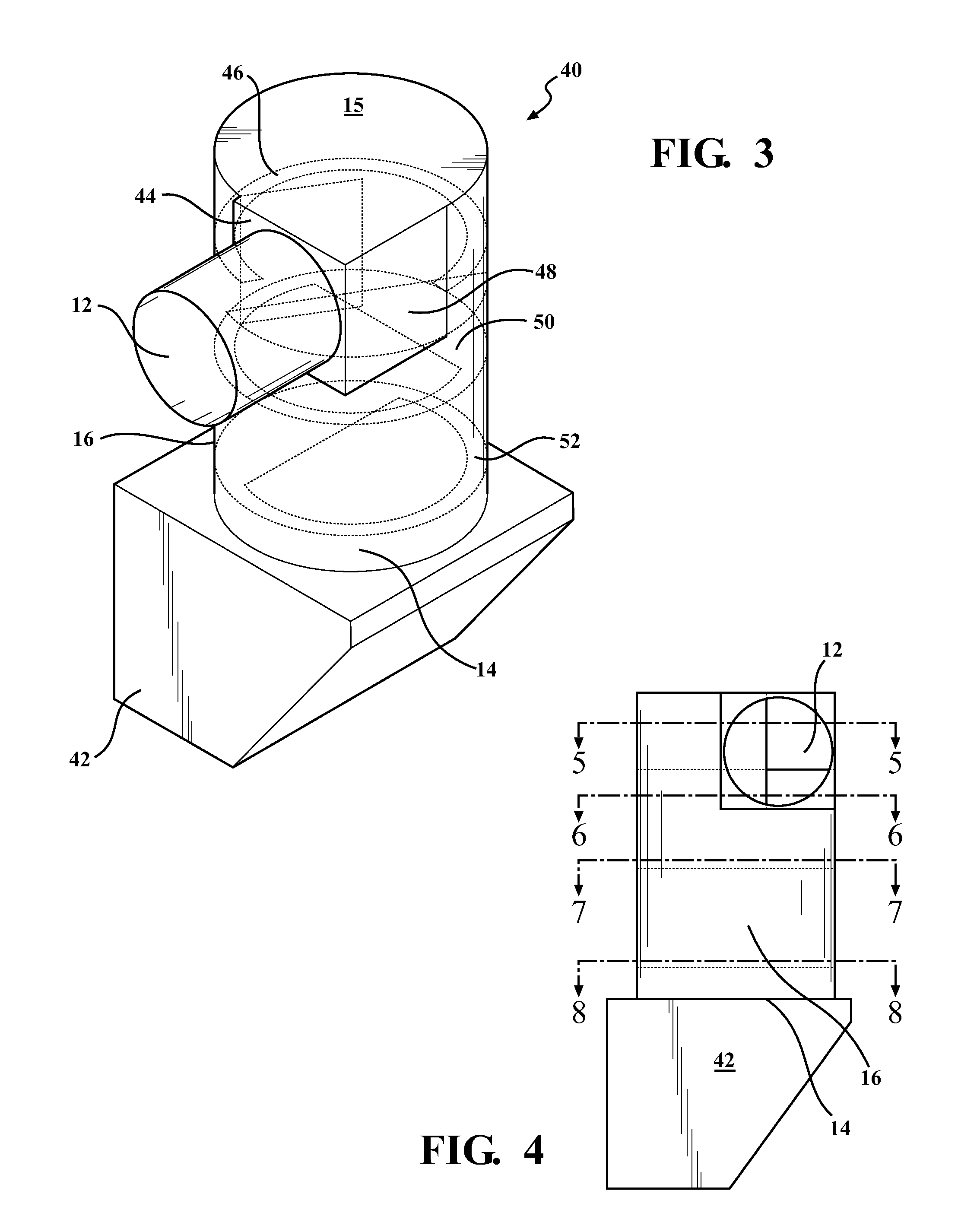
[0037]With reference to FIG. 3, the present invention is shown generally at 40. As with the previous embodiments, there is an inlet 12, an outlet 14 and a main body portion 16. In this embodiment, only one end 15 is closed, the opposite end is open and forms the outlet 14. Mounted within the main body portion 16 adjacent the inlet 12 is a first flow direction plate 44. The plate 44 directs the airflow directly into the inner wall of the body 16 and initiates the centrifugal flow of air. The air initially is forced against a first ring 46 that extends partially around the perimeter of the inner wall of the body 16. Positioned directly below the ring 46 is a partial plate 48 that extends outwardly from the inner wall 16 and partially into the interior of the body 16. Positioned below the partial plate 48 are two generally ring shaped plates 50 and 52, each having a portion cutaway to form openings 54 as shown in FIGS. 7 and 8. The outlet 14 of this embodiment empties into a plenum 42 ...


PUM

PropertyMeasurementUnit
Flow rateaaaaaaaaaa

Abstract

A centrifugal spark arrestor having a main body portion with a first end and a second end spaced from one another. The main body has an interior wall defining a flow path for the flow of air through the main body and a longitudinal axis. An inlet is positioned at the first end and extends generally perpendicular to the longitudinal axis. The inlet is in operative communication with the flow path. An outlet is positioned at the second end; the outlet is in operative communication with the flow path. At least one baffle is positioned within the main body portion between the first and second ends, partially extending into the flow path. Air is pulled into the inlet and forced initially in a direction perpendicular to the longitudinal axis and against the interior wall. The air is forced through the main body portion to the outlet in a centrifugal flow path. The baffle is engaged by the air flowing through the main body portion with any particles entrained within the air impinging upon the baffle.

Description

RELATED APPLICATIONS[0001]This application claims the benefit of U.S. Provisional Application No. 61 / 885,031 filed on Oct. 1, 2013.STATEMENT REGARDING FEDERALLY SPONSORED RESEARCH[0002]NONETECHNICAL FIELD[0003]This invention relates generally to spark arrestors used in commercial and industrial air filtering systems and, more particularly, to a centrifugal spark arrestor assembly.BACKGROUND OF THE INVENTION[0004]Air filtering systems are commonly used in manufacturing facilities, particularly those in which welding, cutting and grinding operations are performed. For example, in a typical welding station located within a manufacturing facility, there is a direct connection, usually through ducting, to an air filtering system. The air filtering system pulls air from the welding station through a series of air filters, filter medium, and then discharges the filtered air back into the facility.[0005]One problem with filtering air from for example a welding, cutting, or grinding operatio...

Claims


Application Information

Patent Timeline
IPC IPC(8): A62C4/00B04C3/06
CPCA62C4/00B04C2003/006B04C3/06B01D45/12B04C2003/003
Inventor REID, JOHNDOUGLAS, JERRYHATTINGH, MIKE
Owner ROBOVENT PROD GRP
Why Eureka
Try Eureka