
Power reception device, power transmission device and vehicle

Active Publication Date: 2015-04-02
TOYOTA JIDOSHA KK
View PDF6 Cites 3 Cited by
  • Summary
  • Abstract
  • Description
  • Claims
  • Application Information

AI Technical Summary

Benefits of technology

The present invention provides a device (a power reception device and a power transmission device) that can accurately measure the temperature of a high-temperature part of a core. This device can be used in vehicles and can help control the temperature of the core, which can improve the performance and efficiency of the vehicle.

Problems solved by technology

Specifically, for example, when an attempt is made to reduce the size of a power reception device and a power transmission device, the heat capacity of a core used in these devices decreases and the allowable temperature of the core decreases.
When the temperature of the core exceeds an allowable value, a loss increases, and the power transfer efficiency decreases or the equipment arranged around the core is affected.

Method used


Image

  • Power reception device, power transmission device and vehicle
  • Power reception device, power transmission device and vehicle
  • Power reception device, power transmission device and vehicle

Examples


Embodiment Construction

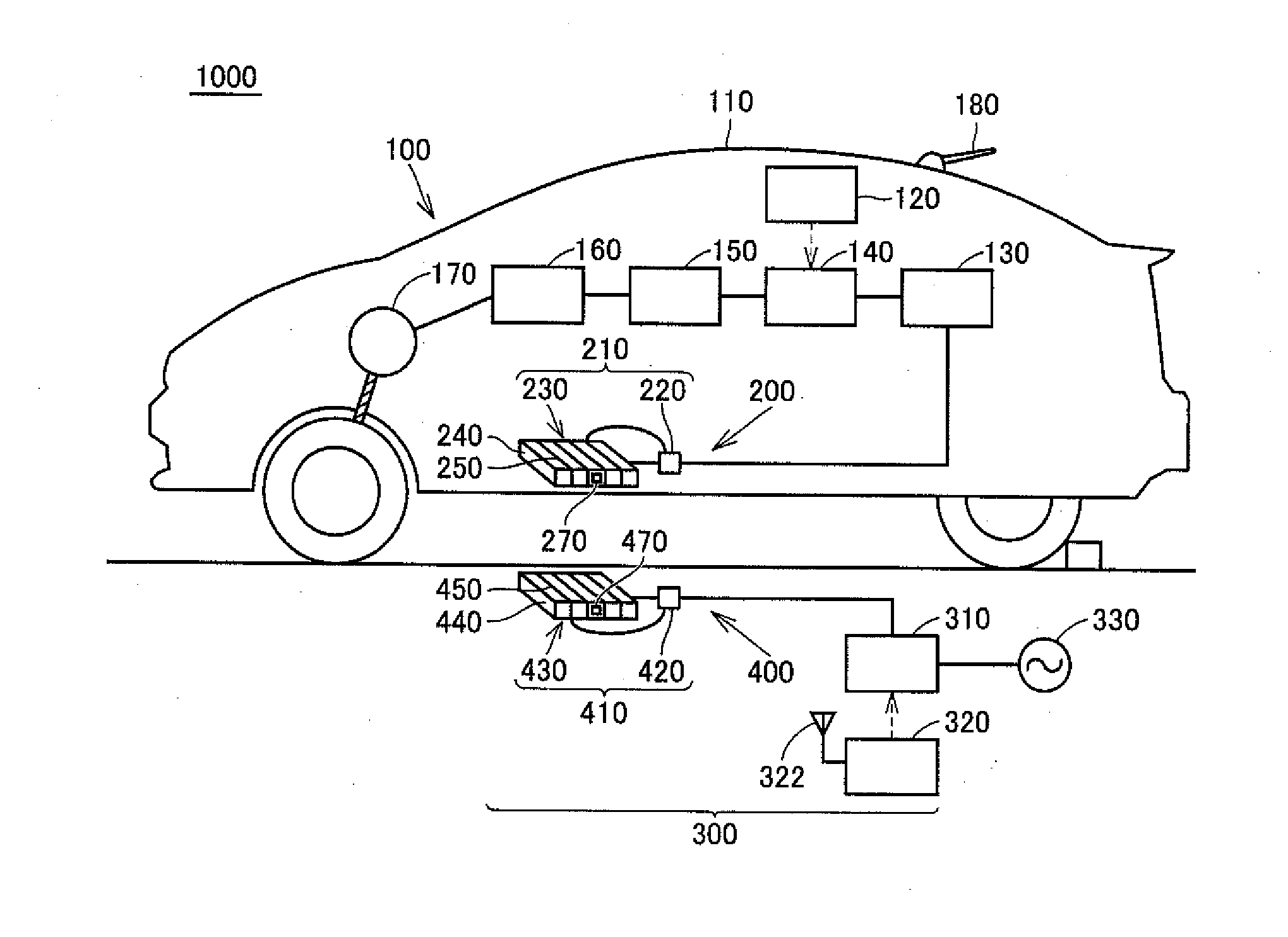
[0042]An embodiment based on the present invention will be described hereinafter with reference to the drawings. When the number, an amount or the like is mentioned in the description of the embodiment, the scope of the present invention is not necessarily limited to that number, that amount or the like, unless otherwise specified. In the description of the embodiment and each example, the same and corresponding components are denoted by the same reference numerals, and redundant description will not be repeated.

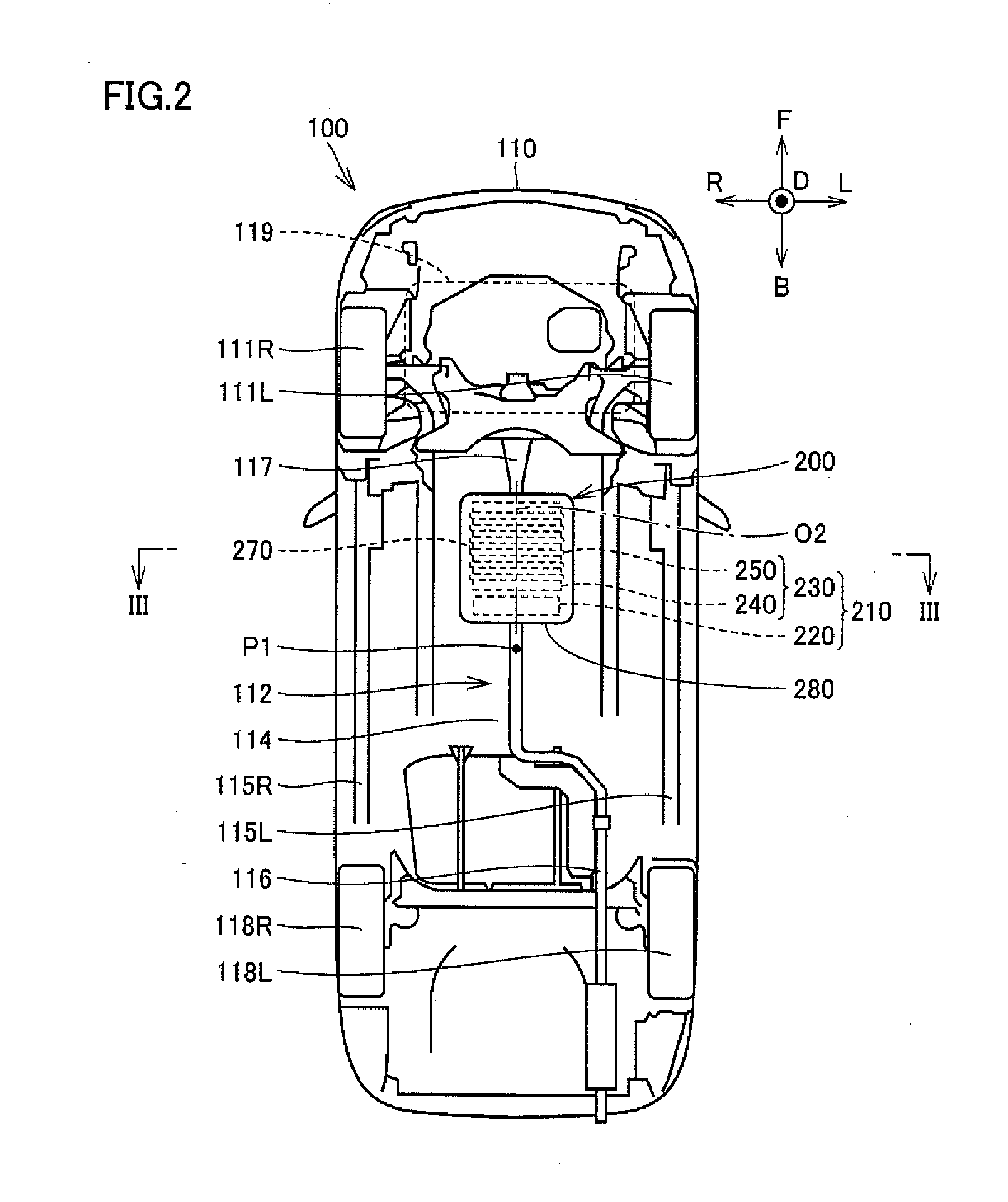
[0043]A power transfer system 1000 in an embodiment will be described with reference to FIG. 1. FIG. 1 is a diagram schematically showing an overall configuration of power transfer system 1000. Power transfer system 1000 includes an electric powered vehicle 100 (vehicle) and an external power feeding device 300. Overall configurations of electric powered vehicle 100 and external power feeding device 300 will be described hereinafter in this order.

[0044](Electric Powered Vehi...


PUM


Abstract

A power reception device includes a core unit having a plate-like shape, a plate-like fixing member having the core unit housed therein, a power reception coil, and a temperature measuring unit. Assuming that a side surface wound portion refers to a portion of a side surface of core unit around which the power reception coil is wound, and a center portion refers to a portion located at the center of the side surface wound portion in an extending direction of a coil winding axis and at the center of the core unit in a thickness direction, temperature measuring unit is provided in at least one of a high-temperature region including the center portion of the core unit and a portion around the center portion, and a position on a surface of the fixing member that faces the high-temperature region.

Description

[0001]This nonprovisional application is based on Japanese Patent Application No. 2013-206387 filed on Oct. 1, 2013 with the Japan Patent Office, the entire contents of which are hereby incorporated by reference.BACKGROUND OF THE INVENTION[0002]1. Field of the Invention[0003]The present invention relates to a power reception device and a power transmission device that receive and transmit electric power in a contactless manner, and a vehicle including the power reception device.[0004]2. Description of the Background Art[0005]As disclosed in Japanese Patent Laying-Open No. 2012-182258, Japanese Patent Laying-Open No. 2013-154815, Japanese Patent Laying-Open No. 2013-146154, Japanese Patent Laying-Open No. 2013-146148, Japanese Patent Laying-Open No. 2013-110822, and Japanese Patent Laying-Open No. 2013-126327, there are known a power reception device and a power transmission device that receive and transmit electric power in a contactless manner. A power reception device disclosed in...

Claims


Application Information

Patent Timeline
IPC IPC(8): B60L11/18H02J5/00B60L5/00B60M7/00H01F38/14
CPCH02J5/005B60L11/182B60L2240/485Y02T10/7072Y02T90/14B60L53/126H02J2310/48Y02T10/70H02J50/005H02J50/70H02J50/80H02J50/12Y02T90/12B60L53/12
Inventor YUASA, HIROAKI
Owner TOYOTA JIDOSHA KK
Learn More