Lensed Base Station Antennas

a base station and antenna technology, applied in the field of radio communication, can solve the problems of increased cost and space requirements, drawbacks of dividing a coverage area into smaller sectors, non-symmetrical beams, etc., and achieve the effect of improving the port-to-port isolation of multi-beam antennas

Active Publication Date: 2015-04-02
MATSING PTE +1
View PDF5 Cites 98 Cited by
  • Summary
  • Abstract
  • Description
  • Claims
  • Application Information

AI Technical Summary

Benefits of technology

[0014]In another aspect of the invention, the multiple beam antenna system may further include a sheet of dielectric material disposed between the radio frequency lens and one or more of the columns of radiating elements. The sheet of dielectric material may further include wires disposed on the sheet of dielectric material. The sheet of dielectric material may further include slots disposed on the sheet of dielectric material. A second sheet of dielectric material may be included for improving port-to port isolation of multi-beam antenna.

Problems solved by technology

However, dividing a coverage area into smaller sectors has drawbacks because antennas covering narrow sectors generally have more radiating elements that are spaced wider than antennas covering wider sectors.
Thus, costs and space requirements increase as a cell is divided into a greater number of sectors.
BFNs, however, have several potential disadvantages, including non-symmetrical beams and problems associated with port-to-port isolation, gain loss, and a narrow band.
And while these lenses can have better performance, the costs of the classic Luneberg lens (a multi-layer, cylindrical lens having different dielectric in each layer) is high and the process of production is extremely complicated.
Additionally, these antenna systems still suffer from several problems, including beam width stability over the wide frequency band and high cross-polarization levels.

Method used


Image

  • Lensed Base Station Antennas
  • Lensed Base Station Antennas
  • Lensed Base Station Antennas

Examples


Embodiment Construction

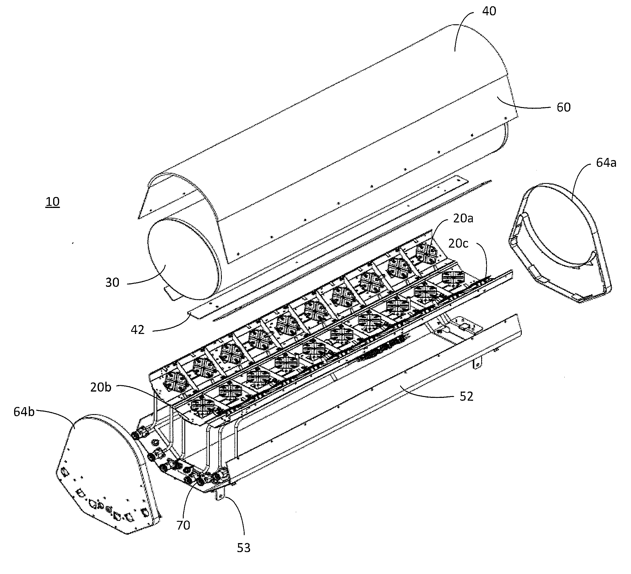
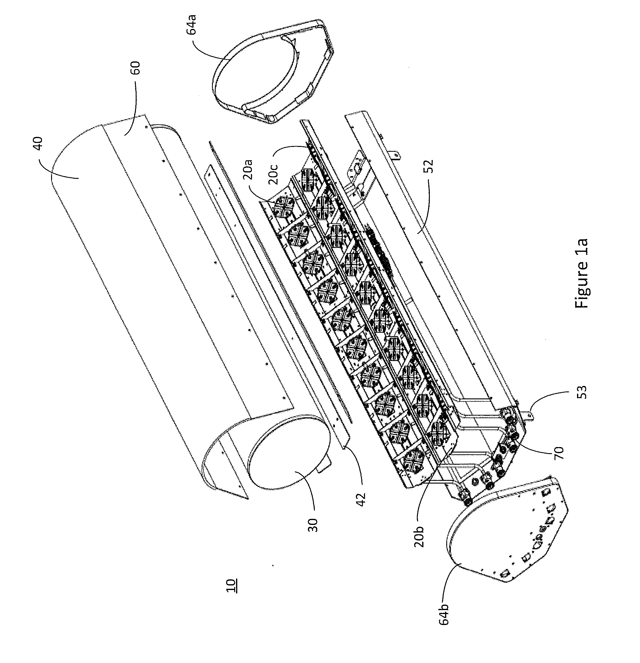
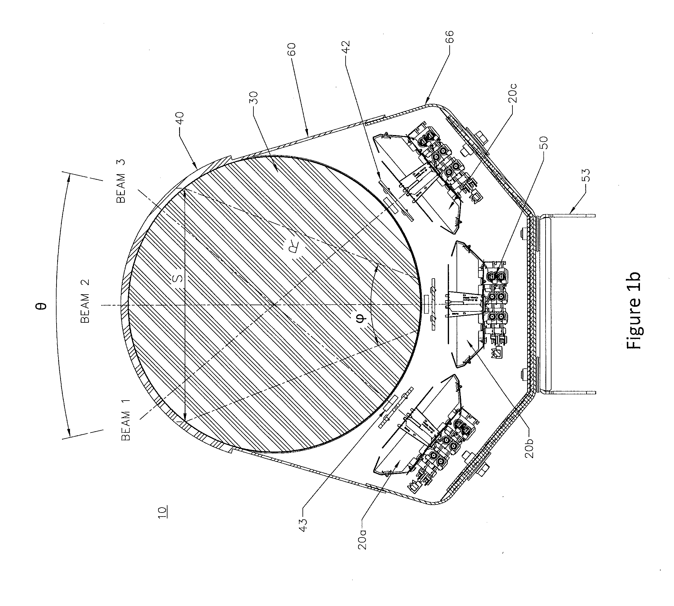
[0045]Referring to the drawings, and initially to FIG. 1a, 1b, an exploded view of one embodiment of a multi-beam base station antenna system 10 is shown in FIG. 1a, and its cross-section is shown in FIG. 1b. In its simplest form, the multi-beam base station antenna system 10 includes one or more linear arrays of radiating elements 20a, 20b, and 20c (also referred to as “antenna arrays” or “arrays” herein) and a radio frequency lens 30. Arrays 20 may have approximately the same length with lens 30. The multi-beam base station antenna system 10 may also include a first compensator 40, a second compensator 42, a secondary lens 43 (shown in FIG. 1b), a reflector 52, radome 60, end caps 64a and 64b, absorber 66 and ports (RF connectors) 70. In description below, azimuth plane is orthogonal to axis of radio frequency lens 30, and elevation plane is in parallel to axis of lens 30.

[0046]In the embodiment shown in FIG. 1a, 1b, the radio frequency lens 30 focuses azimuth beams of arrays 20a,...


PUM


Abstract

A lensed antenna system is provided. The lensed antenna system includes a first column of radiating elements having a first longitudinal axis and a first azimuth angle, and, optionally, a second column of radiating elements having a second longitudinal axis and a second azimuth angle, and a radio frequency lens. The radio frequency lens has a third longitudinal axis. The radio frequency lens is disposed such that the longitudinal axes of the first and second columns of radiating elements are aligned with the longitudinal axis of the radio frequency lens, and such that the azimuth angles of the beams produced by the columns of radiating elements are directed at the radio frequency lens. The multiple beam antenna system further includes a radome housing the columns of radiating elements and the radio frequency lens. There may be more or fewer than two columns of radiating elements.

Description

CROSS REFERENCE TO RELATED APPLICATIONS[0001]This application claims priority to U.S. application Ser. No. 14 / 244,369 filed Apr. 3, 2014 and U.S. Provisional Application Ser. No. 61 / 875,491 filed Sep. 9, 2013, which are hereby incorporated by reference in their entirety.BACKGROUND[0002]The present inventions generally relate to radio communications and, more particularly, to multi-beam antennas utilized in cellular communication systems.[0003]Cellular communication systems derive their name from the fact that areas of communication coverage are mapped into cells. Each such cell is provided with one or more antennas configured to provide two-way radio / RF communication with mobile subscribers geographically positioned within that given cell. One or more antennas may serve the cell, where multiple antennas commonly utilized are each configured to serve a sector of the cell. Typically, these plurality of sector antennas are configured on a tower, with the radiation beam(s) being generat...

Claims


Application Information

Patent Timeline
Patent Type & Authority Applications(United States)
IPC IPC(8): H01Q19/06H01Q15/08H01Q1/42
CPCH01Q19/062H01Q15/08H01Q1/42H01Q1/246H01Q21/062H01Q21/24H01Q21/08H01Q21/06H01Q1/24H01Q19/06
Inventor MATITSINE, SERGUEITIMOFEEV, IGOR E.LINEHAN, KEVIN E.
Owner MATSING PTE
Why Eureka
Try Eureka