Control System For Color Rendering Of Optical Glazings

Inactive Publication Date: 2015-04-02
SAGE ELECTROCHROMICS
View PDF2 Cites 49 Cited by
  • Summary
  • Abstract
  • Description
  • Claims
  • Application Information

AI Technical Summary

Benefits of technology

[0007]In some examples, the quantifiable amount may be one of a percentage of the total surface area of the electronically tintable devices, such as a percentage between about 5% and about 25% of the total surface area of the elec

Problems solved by technology

Setting a section of the device having a glare condition to the high transmittance state

Method used

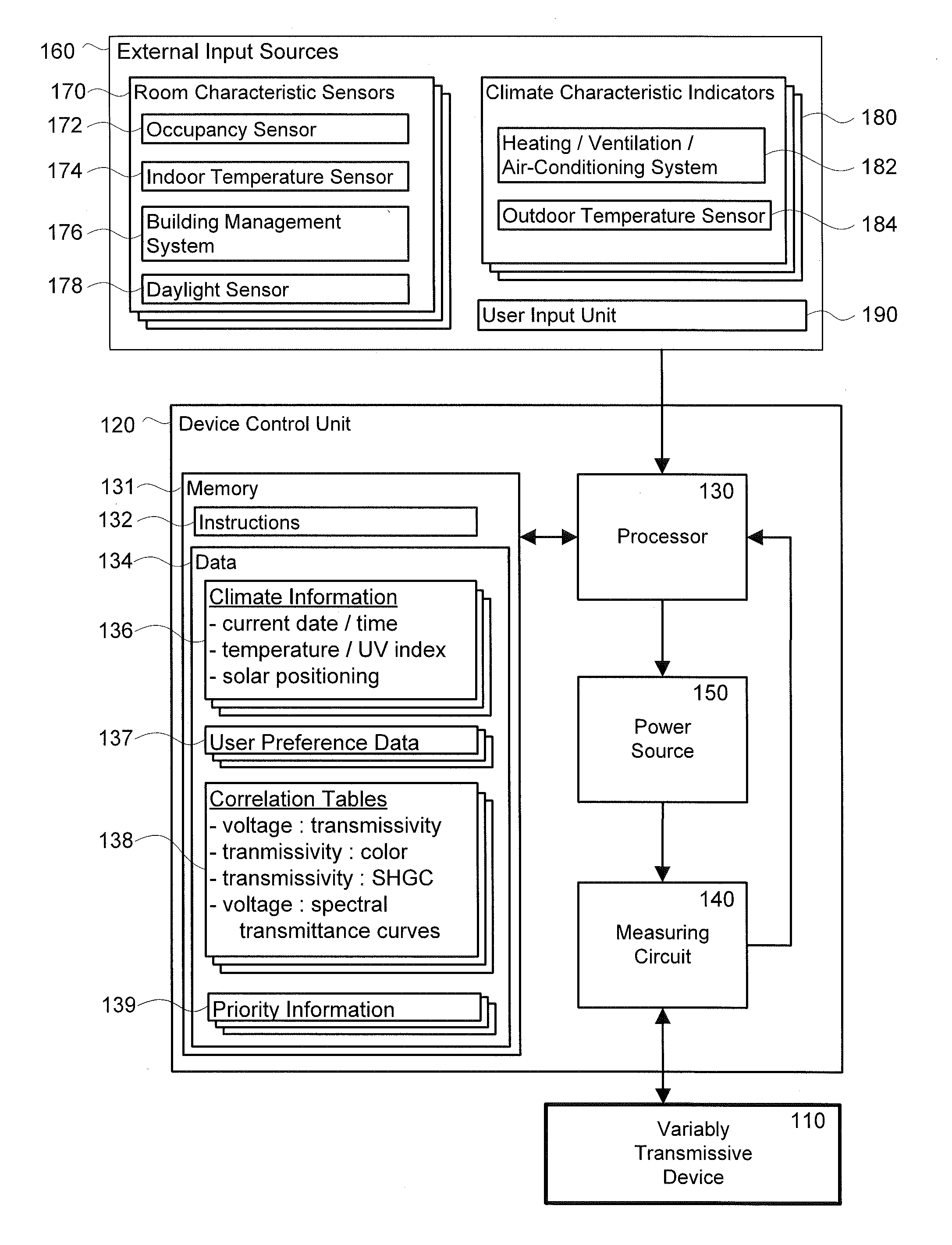
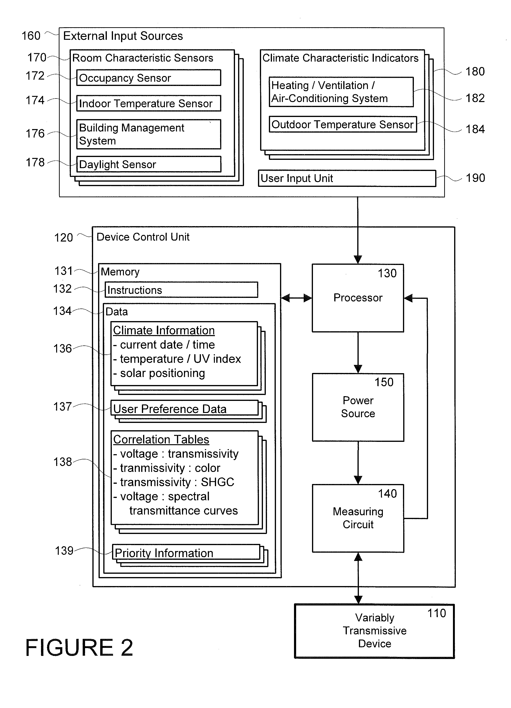

Image

  • Control System For Color Rendering Of Optical Glazings
  • Control System For Color Rendering Of Optical Glazings
  • Control System For Color Rendering Of Optical Glazings

Examples


Embodiment Construction

[0040]One object of the present invention is to provide a system for controlling an electrochromic or other variably transmissive device to maintain an acceptable illumination color spectrum in an interior space associated with the device. It has been found that in most situations maintaining between about 5% and about 25% of the surface area of the device in a high transmittance state (e.g., about 32% transmissivity or above, about 40% transmissivity or above, about 50% transmissivity or above, about 55% transmissivity or above, about 60% transmissivity or above, the highest transmittance state that the device is capable of achieving, within about 10% transmittance of the highest transmittance state, etc.) provides enough color neutral light to maintain an acceptable illumination color spectrum, even while the remaining about 75% to about 95% of the device is in a low transmittance setting (e.g., about 60% transmissivity or below, about 55% transmissivity or below, about 50% transm...


PUM


Abstract

The present disclosure provides for a method of controlling a plurality of independently controllable sections of one or more electrochromic devices belonging to a common interior space to provide lighting having a substantially color neutral or aesthetically pleasing spectrum to the interior space. The method comprises receiving a desired illuminance input indicating an amount of lighting desired in the interior space, and a neutral lighting input indicating a quantifiable amount of the sections of the electrochromic devices to be set to a high transmittance state. One or more sections of the electrochromic devices are selected in accordance with the neutral lighting input. The selected sections of the electrochromic device are set to the high transmittance state. The one or more electrochromic devices collectively transmit an amount of light into the interior space in accordance with the desired illuminance input.

Description

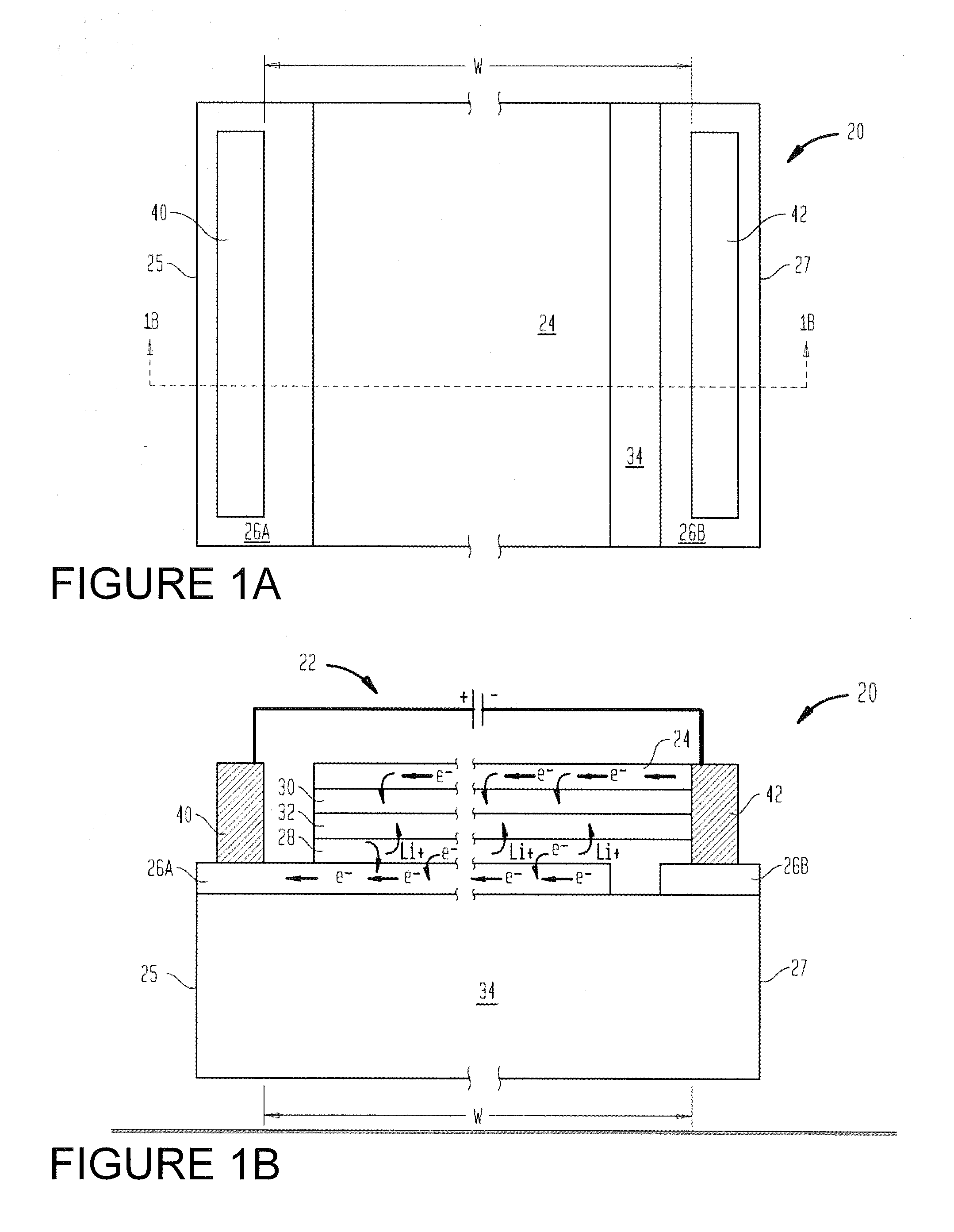
BACKGROUND OF THE INVENTION[0001]Electronically tintable glass, such as electrochromic devices, have been developed as an alternative to passive coating materials for light and heat management in building and vehicle windows. In contrast to passive coating materials, electronically tintable glazings employ materials capable of reversibly altering their optical properties in response to an applied potential.[0002]In general, electronically tintable devices or glazings have a composite structure through which the transmittance of light can be modulated. FIGS. 1A and 1B illustrate plan and cross-sectional views, respectively, of a typical prior art electrochromic device 20. The device 20 includes isolated transparent conductive layer regions 26A and 26B that have been formed on a substrate 34, such as glass or optical glazing. In addition, the device 20 includes a counter electrode layer 28, an ion conductive layer 32, an electrochromic layer 30 and a transparent conductive layer 24, w...

Claims


Application Information

Patent Timeline
IPC IPC(8): G02F1/163F21V23/04
CPCF21V23/0464G02F1/163E06B9/24F21S19/005E06B2009/2464F21V33/006E06B2009/2411H05B47/11Y02B20/40
Inventor GREER, BRYAN D.PODBELSKI, LOUIS J.SANDERS, HELEN
Owner SAGE ELECTROCHROMICS
Why Eureka
Try Eureka