
Mobile fibers and elongated structures and units thereof

a technology of elongated structures and fibers, applied in the direction of connection contact material, non-rotary current collectors, coupling device connections, etc., can solve the problems of inability to easily and reversibly build modularly to reach variable lengths, and none of the prior systems known to combine separate actuation,

Active Publication Date: 2015-04-02
STERN THOMAS
View PDF2 Cites 16 Cited by
  • Summary
  • Abstract
  • Description
  • Claims
  • Application Information

AI Technical Summary

Benefits of technology

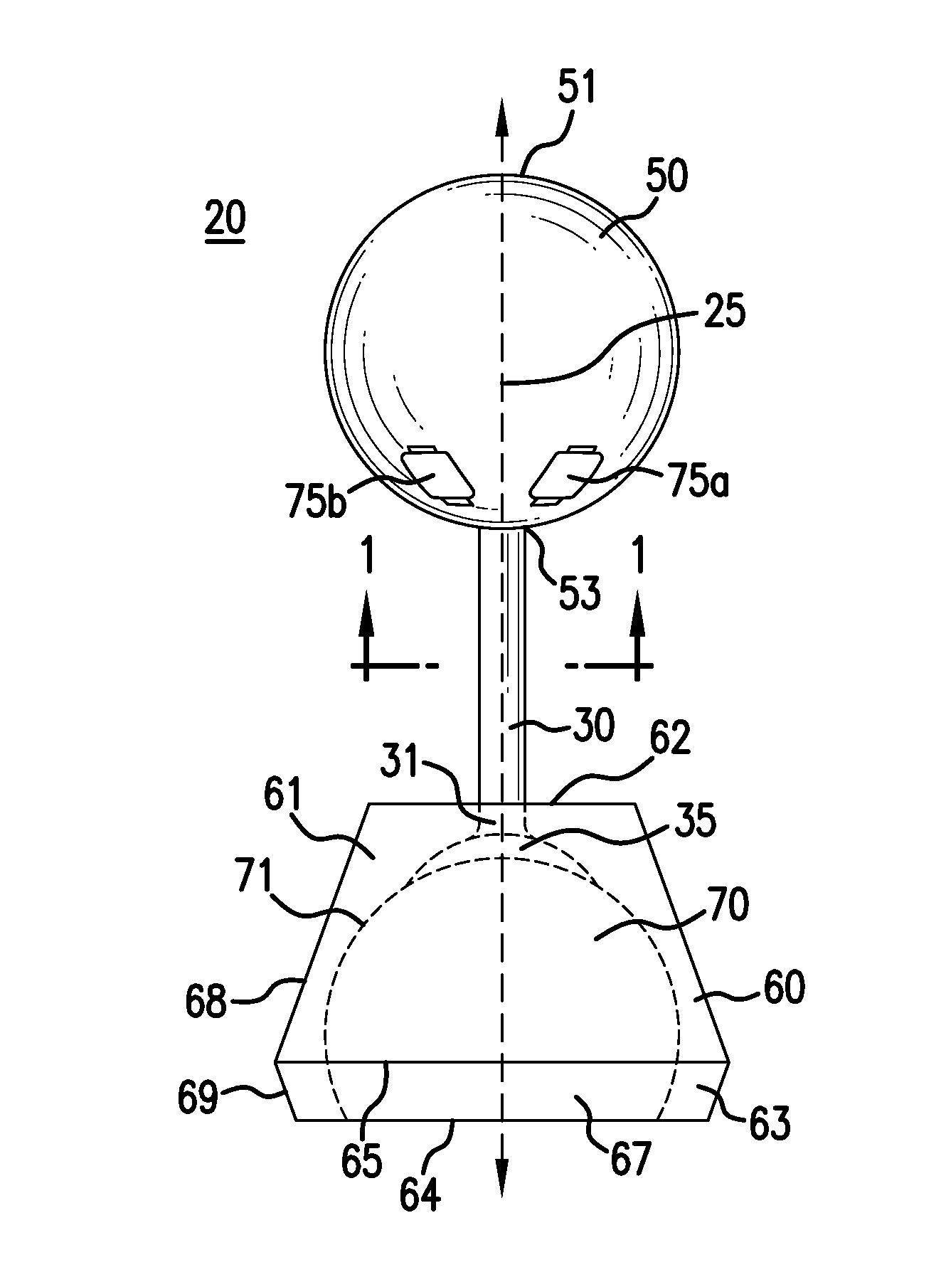
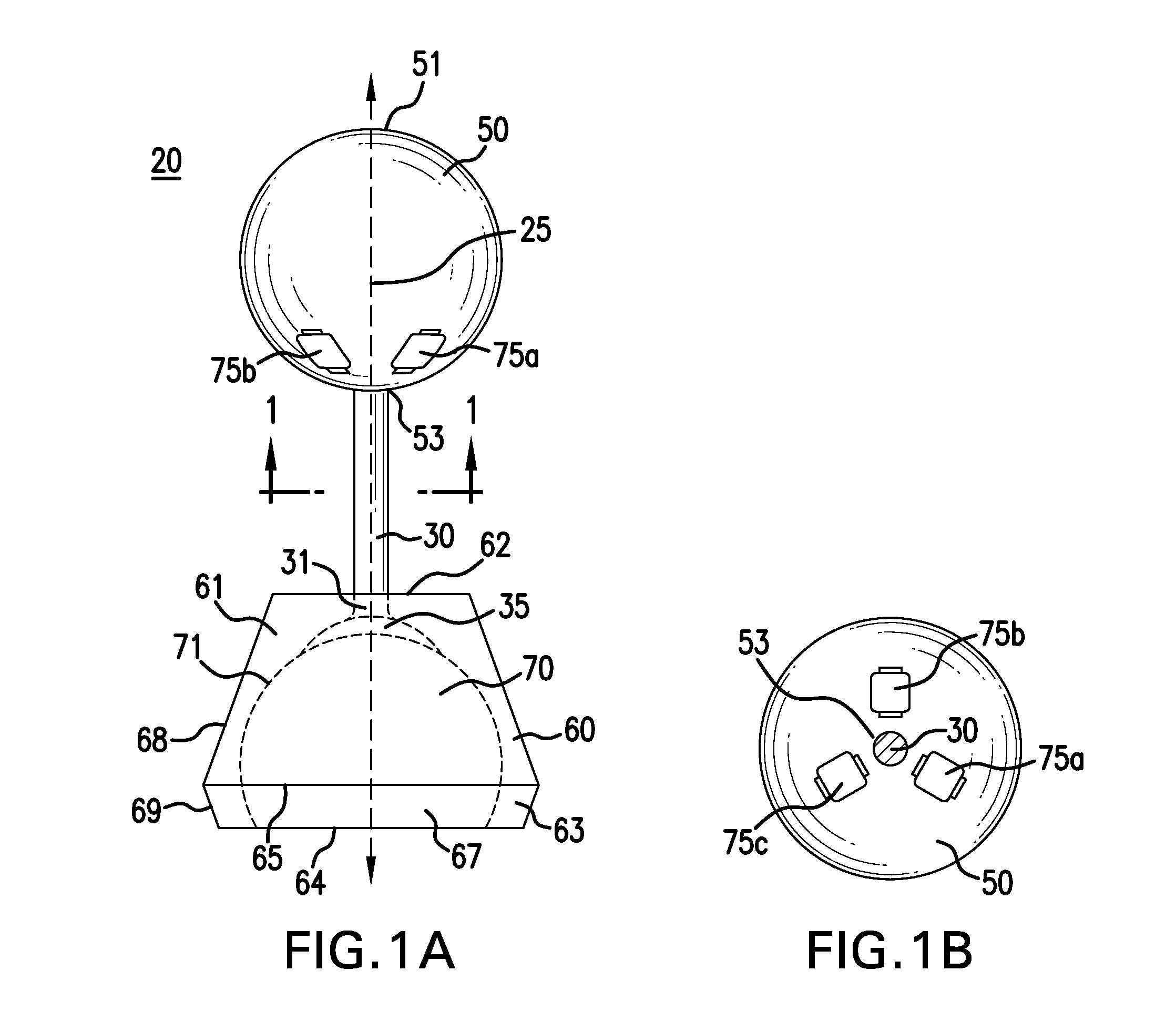
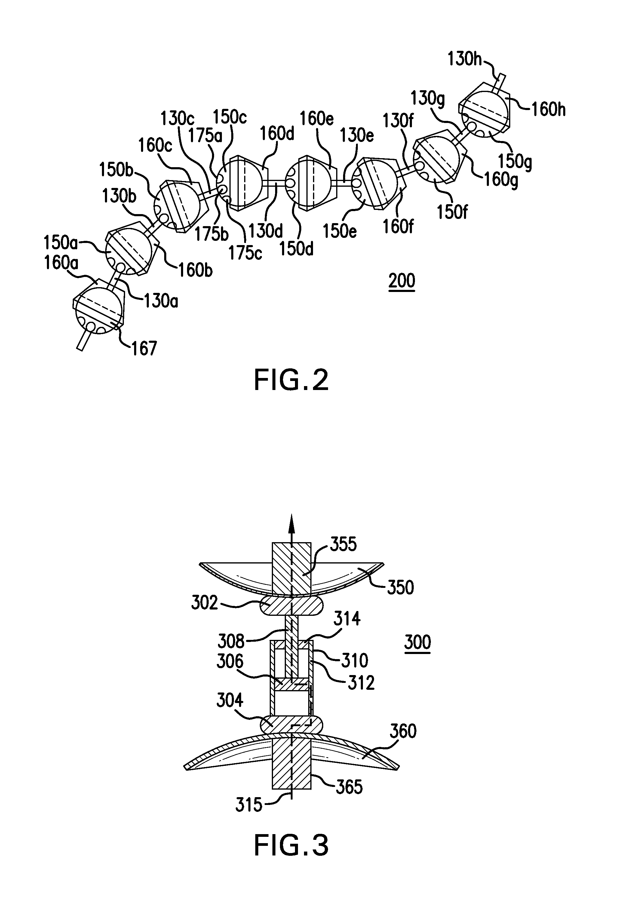
The present invention provides a unit that includes a ball, a socket, and a connector that physically links them together. The ball and socket have a spherical outer shape with opposite ends. The connector has two ends and includes a central conducting channel and lateral conducting channels that provide electrical connections between the ends of the ball. The unit also includes a controller in electrical communication with the conducting channels. The invention also provides an elongated structure that joins multiple units together, where each unit has a ball, a socket, and a connector. The sockets have a continuous opening at the end. The invention provides a more efficient and reliable electrical connection between the units.

Problems solved by technology

However, none of these prior systems are known to combine separate actuating mechanisms for (1) lengthwise elongation / contraction and (2) lateral bending movements in a manner that is simple enough to allow for its reasonable construction and operation on a smaller scale, such as part of a small thread, fiber, etc.
Many prior arm-like devices have only one of these two types of actuating movements and / or require a complex construction.
Many of these prior actuating mechanisms for elongated structures are also constricted in their range of motion and / or unable to be easily and reversibly constructed in a modular fashion to reach variable lengths.

Method used


Image

  • Mobile fibers and elongated structures and units thereof
  • Mobile fibers and elongated structures and units thereof
  • Mobile fibers and elongated structures and units thereof

Examples


Embodiment Construction

[0030]Threads, fibers, strings, cords, ropes, wires, cables, etc., are all examples of elongated structures that may be used for a variety of purposes, such as tying things together, weaving into a fabric, etc. While these elongated structures are generally able to carry out these functions due to their tensile strength, they are inanimate structures until an external force is applied to them. In contrast, the present invention provides elongated structures, such as threads, fibers, strings, etc., and possibly larger arm-like or other elongated structures, comprising a plurality of units or segments that are able to be animated by their controlled, relative movement(s) in a variety of ways. These controllable movements generally include the ability of one or more of the units or segments of the elongated structure, or at least a portion of those units / segments and / or the attachment(s) between them, to (i) extend or contract / retract in length and / or (ii) laterally bend in various dir...


PUM


Abstract

The present invention provides a unit or segment having a ball, a socket and a connector with the connector physically linking the ball and socket together such that a main opening of the socket continuous with the socket cavity faces away from the connected ball. Alternatively, a unit / segment may instead include a ball and a socket coupled directly together. Elongated structures comprising a plurality of units joined together in series, such as through ball joints and other connections, are further provided that may vary greatly in length and size. The ball and socket may have corresponding electromagnets and magnetic materials, respectively, that may attract or repel each other to cause controlled rotational movement of the individual ball joint(s) by controlling the operation of the electromagnets. Higher order structures including one or more elongated structures are further provided. Methods for constructing and / or operating units and / or elongated structures are further provided.

Description

BACKGROUND[0001]1. Field of the Invention[0002]The present invention relates to elongated arms, threads, fibers or other like structures that are able to controllably bend and move variably with undulating or serpentine-like motions.[0003]2. Related Art[0004]Flexible or bendable arm-like structures have been described, such as for robotics, typically to position a distal functional end of the arm, such as a clamp or set of gripping fingers, etc., to carry out an operation in space, such as to hold an object. A number of mechanisms have been described to cause movement or bending of these arm-like structures. However, none of these prior systems are known to combine separate actuating mechanisms for (1) lengthwise elongation / contraction and (2) lateral bending movements in a manner that is simple enough to allow for its reasonable construction and operation on a smaller scale, such as part of a small thread, fiber, etc. Many prior arm-like devices have only one of these two types of ...

Claims


Application Information

Patent Timeline
IPC IPC(8): H01R4/58A41D1/00
CPCH01R4/58B25J9/065B25J18/06H01R13/2478H01R35/04D03D1/0088A41D1/00
Inventor STERN, THOMAS
Owner STERN THOMAS
Learn More