Cover Kit for Portable Electronic Device

Inactive Publication Date: 2015-04-09
KIDAKARN MICHAEL
View PDF7 Cites 0 Cited by
  • Summary
  • Abstract
  • Description
  • Claims
  • Application Information

AI Technical Summary

Benefits of technology

The technical effects of this patent include: providing a portable electronic device with a cover kit that allows users to change the appearance of their device with a desired aesthetic pattern printed on a sheet that can be easily placed on the device's cover; providing a cutting device to cut the aesthetic pattern sheet to fit the cover unit; using an existing printed material, such as a magazine, to create the aesthetic pattern sheet without needing to pay extra copyright licensing fees; and allowing users to conveniently and freely place their desired aesthetic pattern sheet on the cover unit.

Problems solved by technology

One of the main disadvantages the aesthetic patterns of the external covers are usually pre-set and fixed, with no possibility of being changed unless the user purchase another cover with different aesthetic pattern.
However, because such famous or popular characters, patterns are usually subject to copyright protection, the license fee is included in the purchase price of the external cover and this makes the overall price of the external cover very expensive.
As a result, when the user wishes to purchase another external cover because of a newly released aesthetic pattern or he becomes blasé about the old aesthetic pattern printed on the old external cover, the user needs to spend a considerable amount money.
More importantly, the user may not fully like a particular portion of the aesthetic pattern.
However, because all the designs of the aesthetic patterns are pre-set and pre-printed on the external cover, the user has no choice but to purchase it.
This practice involves considerable waste of money and resources.

Method used


Image

  • Cover Kit for Portable Electronic Device
  • Cover Kit for Portable Electronic Device
  • Cover Kit for Portable Electronic Device

Examples


Embodiment Construction

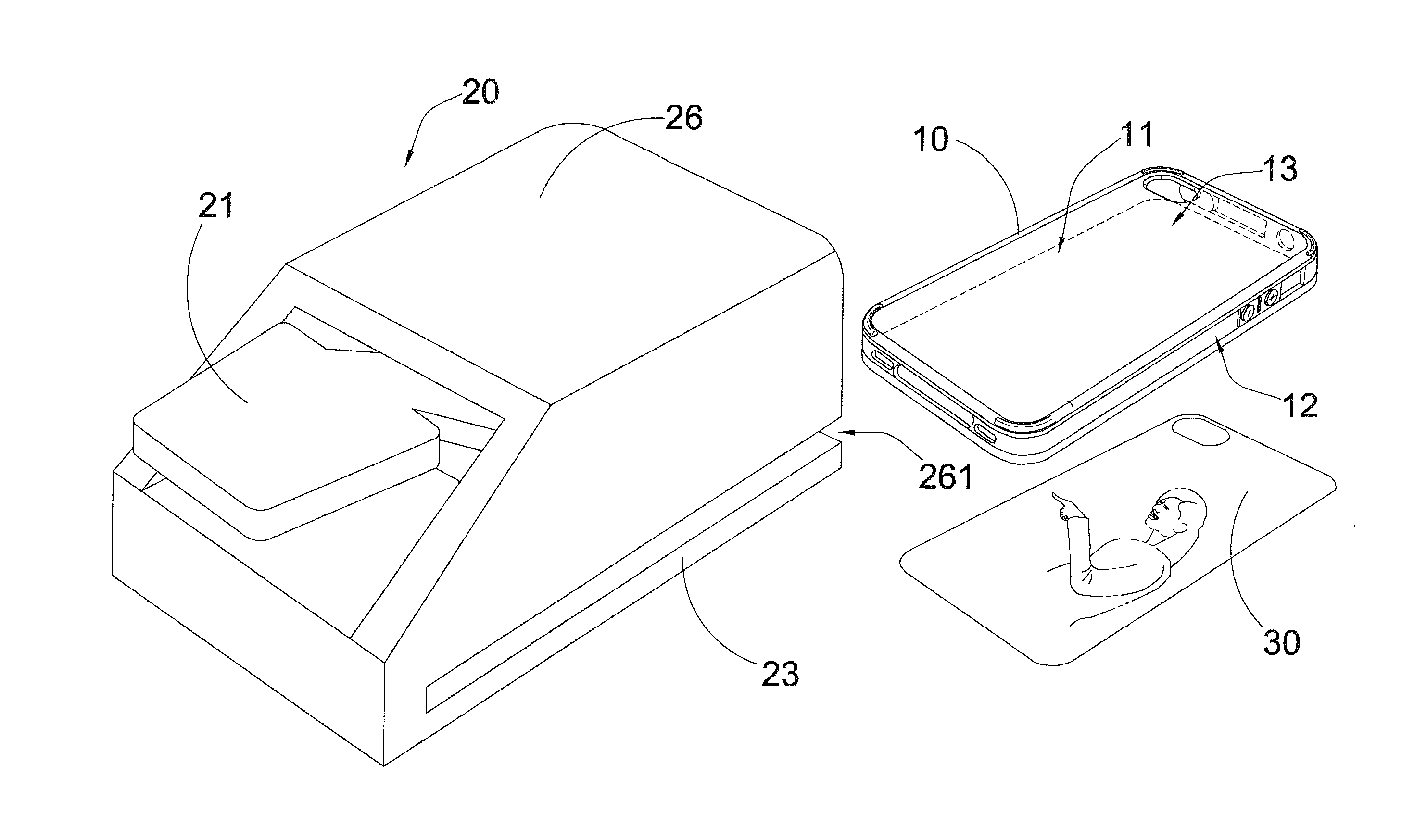
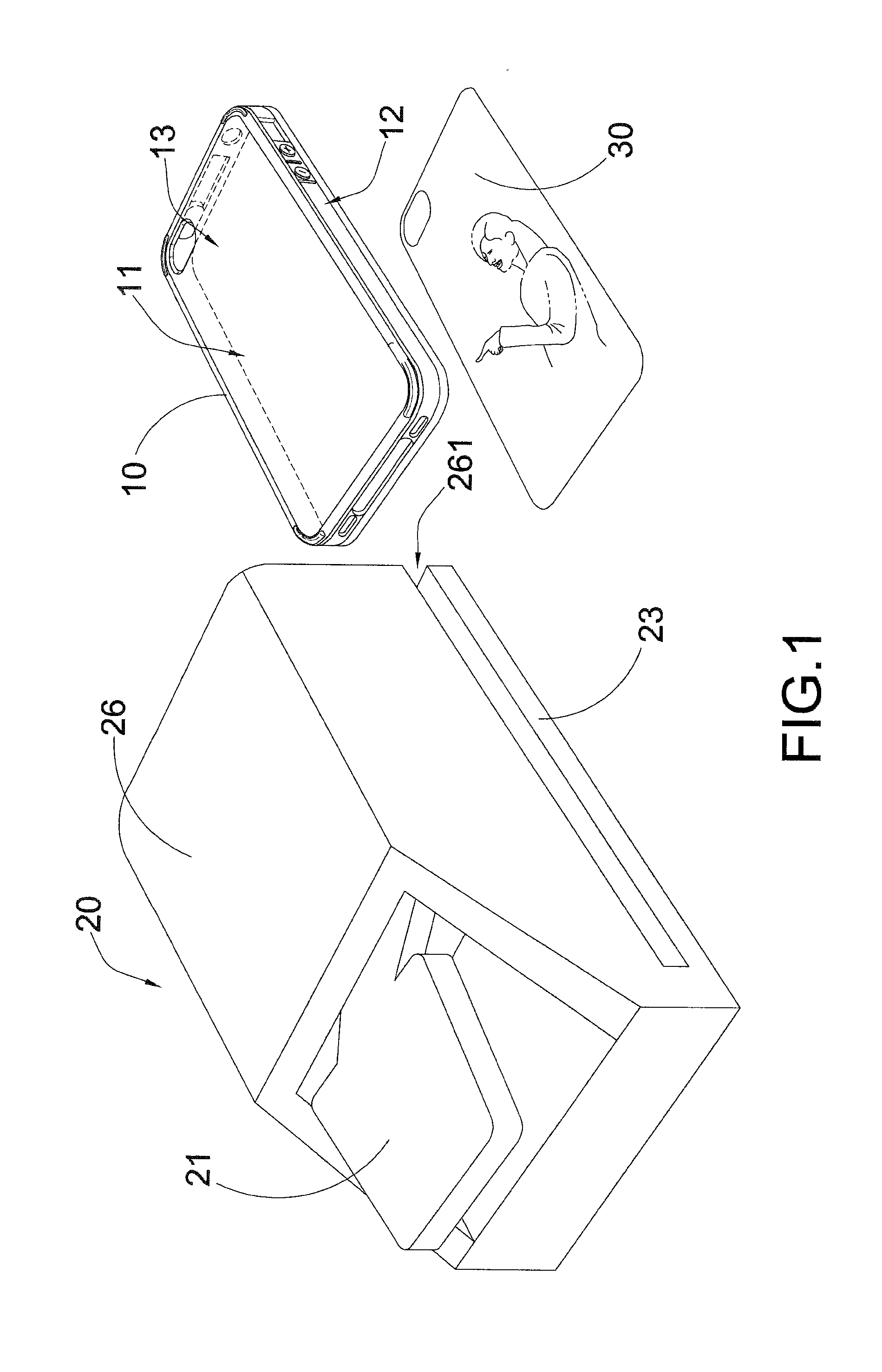
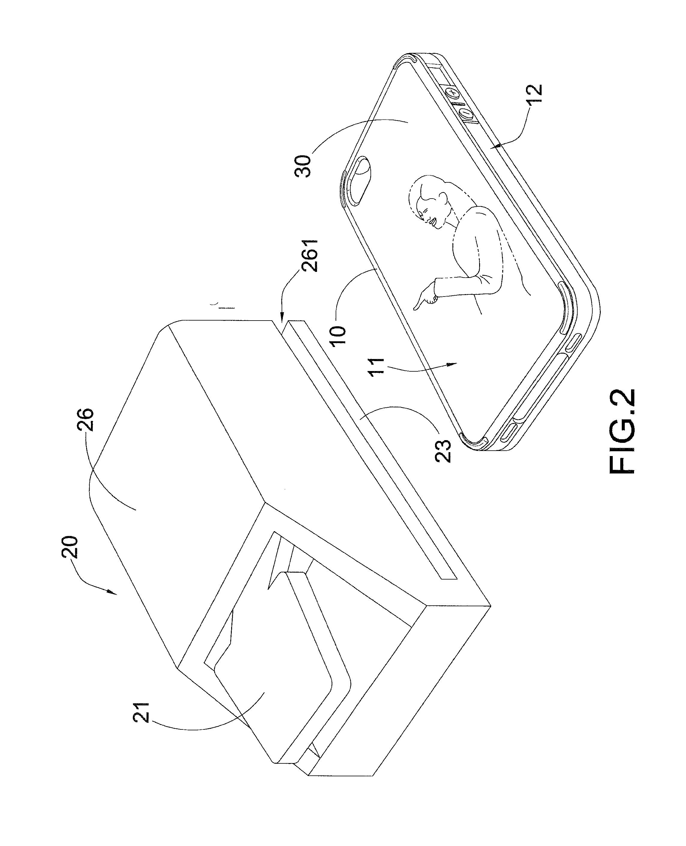
[0024]Referring to FIG. 1 to FIG. 2 of the drawings, a cover kit for a portable electronic device 70 according to a preferred embodiment of the present invention is illustrated, in which the cover kit comprises a cover unit 10 and a stamp unit 20.

[0025]The cover unit 10 has a transparent panel 11, a plurality of side boundary walls 12 peripherally extended from the transparent panel 11 to define a receiving cavity 13 between the transparent panel 11 and the side boundary walls 12, wherein the receiving cavity 13 is shaped and sized to fittedly and detachably receive the portable electronic device 70 therein.

[0026]The stamp unit 20 is adapted for cutting a predetermined printed material, such as a desirable magazine paper, to form an aesthetic pattern sheet 30, wherein the aesthetic pattern sheet 30 has a predetermined aesthetic pattern formed thereon, and is adapted for accommodating on the receiving cavity 13 in such a manner that the aesthetic pattern is capable of being observed ...


PUM

PropertyMeasurementUnit
Transparencyaaaaaaaaaa
Plasticityaaaaaaaaaa

Abstract

A cover kit for a portable electronic device includes a cover unit and a stamp unit. The cover unit has a transparent panel, a plurality of side boundary walls peripherally extended from the transparent panel to define a receiving cavity between the transparent panel and the side boundary walls, wherein the receiving cavity is shaped and sized to fitly and detachably receive the portable electronic device. The stamp unit is adapted for cutting a predetermined printed material to form an aesthetic pattern sheet, wherein the aesthetic pattern sheet has a predetermined aesthetic pattern formed thereon, and is adapted for accommodating on the receiving cavity in such a manner that the aesthetic pattern is capable of being observed from the transparent panel.

Description

BACKGROUND OF THE PRESENT INVENTION[0001]1. Field of Invention[0002]The present invention relates to a cover kit, and more particularly to a cover kit for a portable electronic device, wherein the cover kit is capable of allowing a user to conveniently select and adopt a predetermined aesthetic patterns on a cover body.[0003]2. Description of Related Arts[0004]Users of portable electronic devices, such as smart phones, usually purchase an external cover to partially or fully embed the portable electronic devices in an attempt to protect the devices from external impacts or stretches. One of the main disadvantages the aesthetic patterns of the external covers are usually pre-set and fixed, with no possibility of being changed unless the user purchase another cover with different aesthetic pattern.[0005]Recently, external covers as described above have become a kind of fashion along users of portable electronic devices. Thus, many people want his or her external cover to bear the aest...

Claims


Application Information

Patent Timeline
IPC IPC(8): B26F1/40B26F1/44B44C1/16
CPCB26F1/40B26F2001/4481B26F1/44B44C1/16Y10T83/8821Y10T156/1062
Inventor KIDAKARN, MICHAEL
Owner KIDAKARN MICHAEL
Why Eureka
Try Eureka