Additive Manufacturing for Radio Frequency Hardware

a technology of additive manufacturing and radio frequency hardware, applied in the field of manufacturing, can solve the problems of affecting the functionality of the device, the device is not functional, and the device is not suitable for use,

Active Publication Date: 2015-04-09
THE BOEING CO
View PDF6 Cites 25 Cited by
  • Summary
  • Abstract
  • Description
  • Claims
  • Application Information

AI Technical Summary

Problems solved by technology

Further, the quality of manufacture of the passive radio frequency devices may influence the functionality of the devices.
For example, the surface roughness of passive radio fr

Method used


Image

  • Additive Manufacturing for Radio Frequency Hardware
  • Additive Manufacturing for Radio Frequency Hardware
  • Additive Manufacturing for Radio Frequency Hardware

Examples


Embodiment Construction

[0020]The different illustrative embodiments recognize and take into account a number of different considerations. For example, the different illustrative embodiments recognize and take into account that additive manufacturing equipment may form structures having undesirable surface roughness. Specifically, the different illustrative embodiments recognize and take into account that additive manufacturing equipment may form passive radio frequency devices having undesirable surface roughness. This undesirable surface roughness may undesirably affect the functionality of passive radio frequency devices.

[0021]The different illustrative embodiments recognize and take into account that sanding or grinding of a surface having undesirable surface roughness may not result in a desired surface roughness. The different illustrative embodiments recognize and take into account that sanding may result in parallel scratches or gouges in a surface. These parallel scratches or gouges may result due...


PUM

PropertyMeasurementUnit
Thicknessaaaaaaaaaa
Angleaaaaaaaaaa
Angleaaaaaaaaaa

Abstract

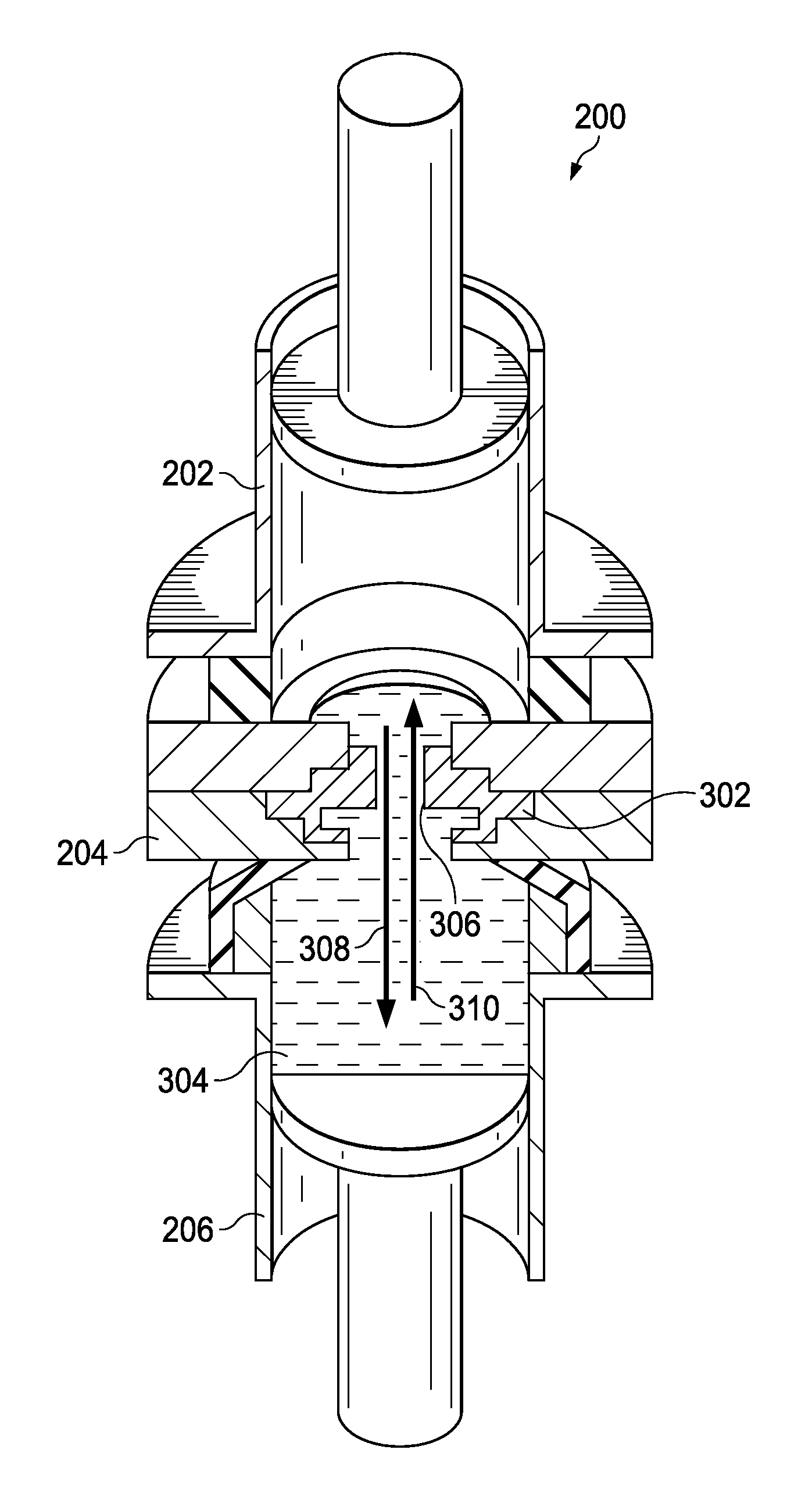
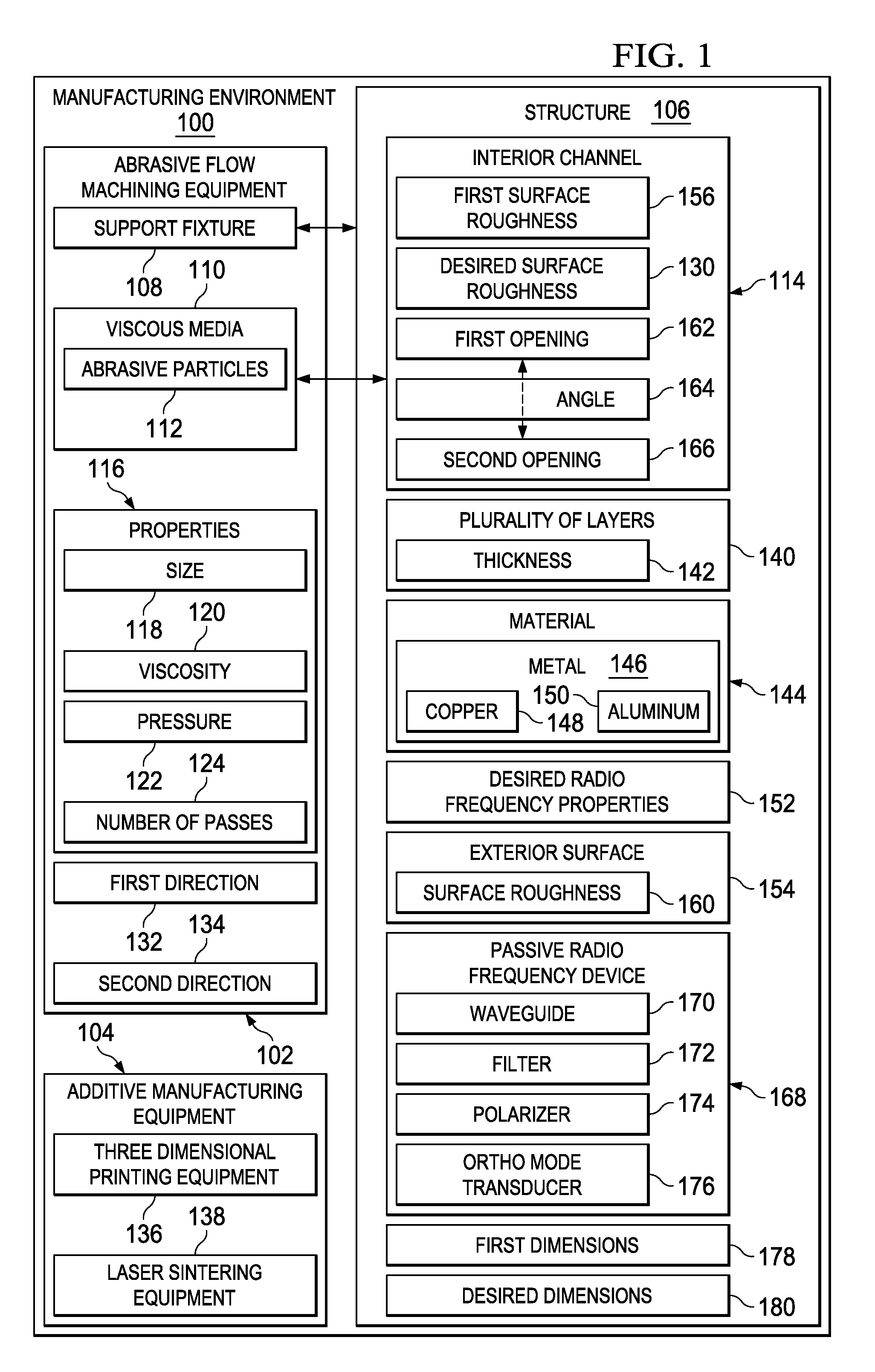
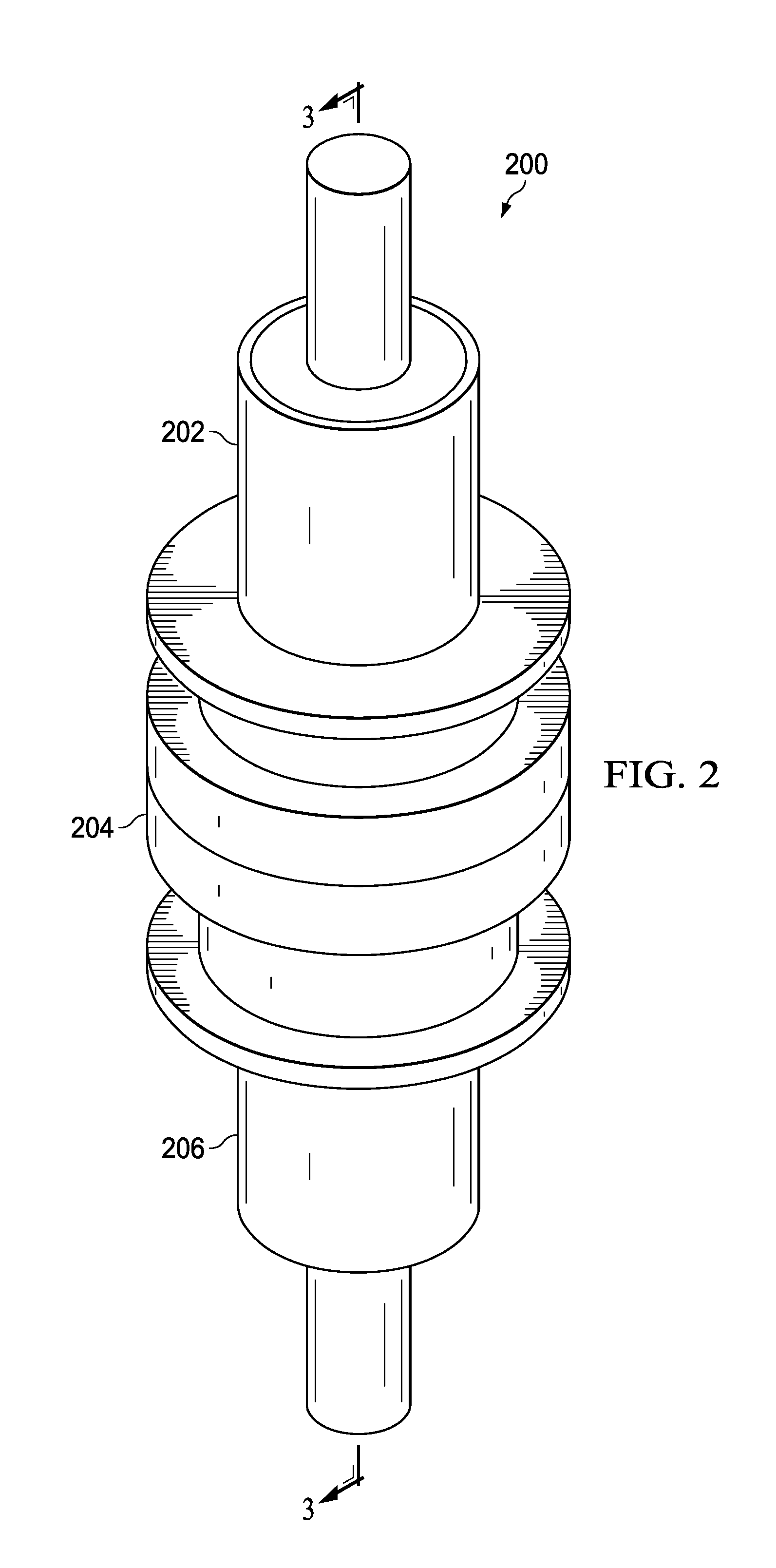
A method and apparatus is presented. A structure having an interior channel is formed using additive manufacturing equipment. A viscous media containing abrasive particles is sent through the interior channel using abrasive flow machining equipment to form a desired surface roughness for the interior channel.

Description

BACKGROUND INFORMATION[0001]1. Field[0002]The present disclosure relates generally to manufacturing and, in particular, to manufacturing radio frequency hardware. Still more particularly, the present disclosure relates to methods and apparatuses for manufacturing radio frequency hardware using additive manufacturing.[0003]2. Background[0004]Passive radio frequency devices may be used to receive, direct, or process waves within the radio frequency spectrum. Passive radio frequency devices may be hardware manufactured in shapes to receive, direct, or process radio frequency waves. The shape and material of manufacture of the passive radio frequency devices may influence the functionality of the devices. Further, the quality of manufacture of the passive radio frequency devices may influence the functionality of the devices.[0005]For example, the surface roughness of passive radio frequency devices may affect the functionality of the devices. Undesirable surface roughness may cause und...

Claims


Application Information

Patent Timeline
IPC IPC(8): H01Q13/00B24B1/00
CPCB24B1/00H01Q13/00B24B31/116H01P11/002
Inventor WILSON, ALLEN WAYNEPATTAMANUCH, PATRICK CHALITROSENHECK, LEONARD
Owner THE BOEING CO
Why Eureka
Try Eureka