Clamp for hydraulic cylinder abrasive flow machining

A hydraulic cylinder and abrasive flow technology, which is applied in the direction of manufacturing tools, metal processing equipment, abrasives, etc., can solve the problems of flow channel flow performance limitations and few applications, and achieve the effects of high processing efficiency, convenient use, and simple structure

Active Publication Date: 2018-12-07
CHANGCHUN UNIV OF SCI & TECH
View PDF4 Cites 4 Cited by
  • Summary
  • Abstract
  • Description
  • Claims
  • Application Information

AI Technical Summary

Problems solved by technology

At present, the application of abrasive flow processing has been continuously improved. Since the flowing medium is guided to the part of the workpiece to be ground during abrasive flow processing, the design of the fixture is very important for abrasive flow processing. The current abrasive flow fixture is generally used in the processing of the outer surface and the through hole, but for the blind hole processing of the hydraulic cylinder, because the flow performance of the flow channel is limited, it is still not suitable for the processing of the hydraulic cylinder. Therefore, how to design an abrasive flow machining fixture for processing the inner wall of the hydraulic cylinder is extremely important for high-performance hydraulic cylinders

Method used


Image

  • Clamp for hydraulic cylinder abrasive flow machining

Examples


Embodiment Construction

[0027] The following will clearly and completely describe the technical solutions in the embodiments of the present invention with reference to the accompanying drawings in the embodiments of the present invention. Obviously, the described embodiments are only some, not all, embodiments of the present invention. Based on the embodiments of the present invention, all other embodiments obtained by persons of ordinary skill in the art without making creative efforts belong to the protection scope of the present invention.

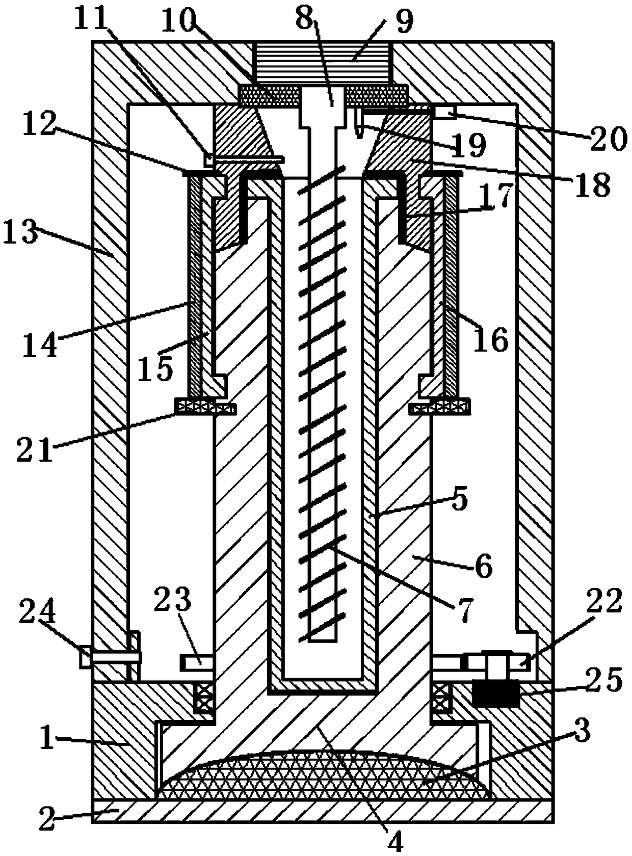
[0028] see figure 1 , the present invention provides a technical solution: a hydraulic cylinder abrasive flow processing fixture, which includes a base 1, a bottom plate 2, a convex ball seat 3, a rotating seat 4, a hydraulic cylinder clamping seat 6, a spiral disc 7, a rotating rod 8. The upper fixing seat 13 and the upper cover seat 18 are characterized in that,

[0029] The base 1 is provided with the convex ball seat 3, the lower end plane of the convex b...


PUM


Abstract

The invention discloses a clamp for hydraulic cylinder abrasive flow machining. The clamp comprises a base, a bottom plate, a convex ball base, a rotating base, a hydraulic cylinder clamping base, a spiral disc, a rotation rod, an upper fixed base and an upper cover base; when abrasive flow finish machining is carried out a hydraulic cylinder, the hydraulic cylinder can be rapidly clamped, duringclamping, a connecting pin only needs to be detached, the upper fixed base is taken down, an outer lock sleeve of an axial connecting assembly is drawn out, a first connecting clamping ring and a second connecting clamping ring are separated, the upper cover base and the hydraulic cylinder clamping base are separated, the hydraulic cylinder is fixed into the hydraulic cylinder clamping base, the axial connecting assembly is mounted, the upper fixed base is positioned, the connecting pin is connected, abrasive flow media are led in, the rotating rod and the rotating base are started, and rotatein the opposite directions, the abrasive flow media can achieve impact machining on the surface of the hydraulic cylinder under rotation of the spiral disc, machining efficiency is high, and the finish machining of the surface of the hydraulic cylinder can be comprehensively achieved.

Description

technical field [0001] The invention relates to a clamp for hydraulic cylinder abrasive flow processing, which belongs to the technical field of abrasive flow clamping equipment. Background technique [0002] A hydraulic cylinder is a commonly used hydraulic actuator that converts hydraulic energy into mechanical energy and performs linear reciprocating motion (or swing motion). It has simple structure and reliable operation. When it is used to realize reciprocating motion, the deceleration device can be eliminated, and there is no transmission gap, and the motion is stable, so it is widely used in various mechanical hydraulic systems. When the hydraulic cylinder is in operation, due to the tight fit between the piston and the inner wall of the hydraulic cylinder, the machining accuracy and surface quality of the inner wall of the hydraulic cylinder have an extremely important impact on the performance and life of the hydraulic cylinder. At present, the inner wall of the h...

Claims


Application Information

Patent Timeline
Patent Type & Authority Applications(China)
IPC IPC(8): B24C9/00
CPCB24C9/00
Inventor 李俊烨朱旭许颖张心明赵伟宏范景峰刘建河周化文
Owner CHANGCHUN UNIV OF SCI & TECH
Why Eureka
Try Eureka