
Clamp for polishing of auto-rotation abrasive flow of rotator workpiece and design method thereof

A design method and self-rotation technology, applied in grinding/polishing equipment, machine tools for surface polishing, machine tools suitable for grinding the edge of workpieces, etc., can solve the problem that the clamping point cannot be polished, the contact between the workpiece and the fixture is damaged, and the rotation Eliminate the uneven material removal on the surface of the workpiece, achieve the effect of convenient mold assembly and disassembly, improve the uniformity of surface processing, and reduce surface roughness

Active Publication Date: 2017-01-04
DALIAN UNIV OF TECH
View PDF9 Cites 4 Cited by
  • Summary
  • Abstract
  • Description
  • Claims
  • Application Information

AI Technical Summary

Problems solved by technology

[0005] In order to solve the above-mentioned problems existing in the prior art, the present invention is to design a method that can not only improve the processing efficiency of the finishing process of the rotary workpiece, reduce the processing cost, and realize mass production, but also solve the problem of uneven material removal on the surface of the rotary workpiece. Fixtures and Design Method for Self-rotating Abrasive Flow Polishing of Revolving Workpieces that Cannot be Polished at Clamping Points and Damaged by Contact between Workpieces and Fixtures

Method used


Image

  • Clamp for polishing of auto-rotation abrasive flow of rotator workpiece and design method thereof
  • Clamp for polishing of auto-rotation abrasive flow of rotator workpiece and design method thereof
  • Clamp for polishing of auto-rotation abrasive flow of rotator workpiece and design method thereof

Examples


Embodiment Construction

[0039] The present invention will be further described below in conjunction with the accompanying drawings.

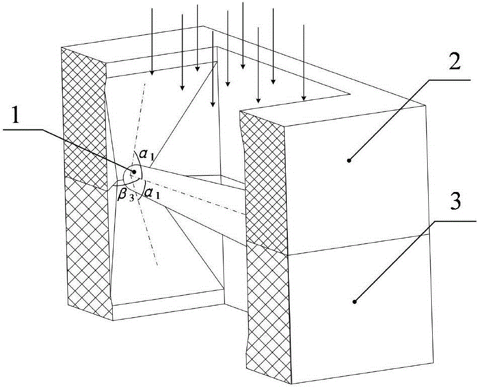
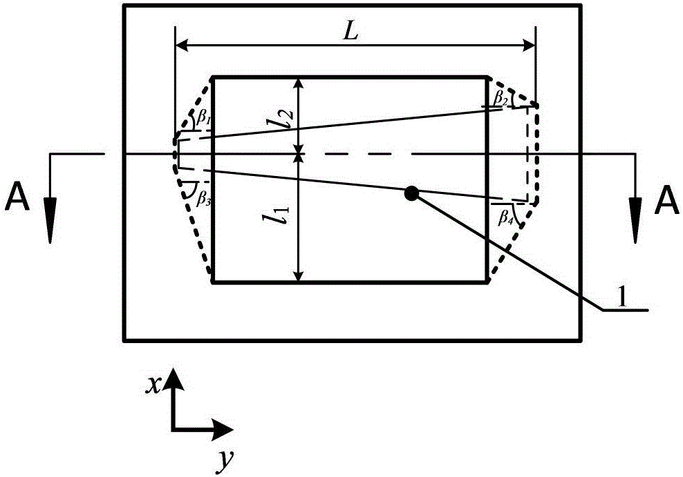
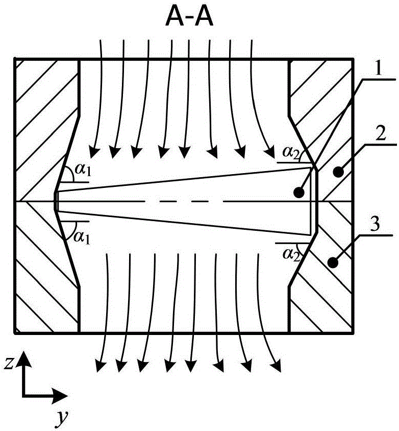
[0040] figure 1 It is a schematic diagram of the eccentric clamping method and the flow channel of the workpiece 1, and is also a schematic diagram of the structure of a single mold 7, Figure 2-3Shown is a schematic diagram of clamping for the non-clamping eccentric rotating abrasive flow machining method of the rotary workpiece 1 (the arrow in the figure is the direction of abrasive flow). It can be seen from the figure that the size of the flow channel is selected according to the actual size of the workpiece 1 , the choice of runner size should ensure the following conditions:

[0041] (1) if Figure 2-3 The size L of the flow channel shown should be approximately equal to and slightly larger than the size of the workpiece 1. On the one hand, it can ensure the smooth clamping of the workpiece 1 during batch processing. On the other hand, it can ensure that the wo...


PUM


Abstract

The invention discloses a clamp for polishing of auto-rotation abrasive flow of a rotator workpiece and a design method thereof. The clamp comprises a clamp base and moulds, wherein the moulds are uniformly distributed in the clamp base in a layered manner, both an upper cover plate and a lower cover plate of the clamp base are provided with a plurality of runner through holes, the clamp base is used for positioning the moulds and supporting pressure of an external machine tool, each mould comprises an upper runner plate and a lower runner plate which are oppositely fastened to form a runner for storing a workpiece to be machined, and the upper runner plates and the lower runner plates are made of materials with low hardness. An untight clamping mode is proposed, movement of the workpiece is limited by setting sizes of the runners of the moulds and inclination angles of wall surfaces, and the clamp solves the problem that a machined workpiece needing complete polishing has no clamping points. Compared with a non-eccentric rotation abrasive flow machining method, the design method has the advantages that surface machining uniformity is improved, and surface roughness and production cost are reduced.

Description

technical field [0001] The invention relates to a technology for finishing the surface of a revolving workpiece, in particular to an abrasive flow polishing method suitable for a revolving workpiece. Background technique [0002] The surface finish processing of revolving workpieces such as warheads, bearing rotors, etc. has the characteristics of large processing batches and high surface quality requirements. The revolving workpieces processed by casting, die-casting and other processing methods have a thicker surface oxide layer and larger surface defects. , and the normal use of rotary workpieces requires high roundness and cylindricity, so there are high requirements for surface processing uniformity and removal volume, so traditional processing methods have high processing costs, low efficiency, and uniformity. Difficult to guarantee such defects. [0003] The existing polishing technology for rotary workpieces generally adopts chemical polishing, light decoration poli...

Claims


Application Information

Patent Timeline
IPC IPC(8): B24B31/116B24B31/12B24B41/06B24C3/32B24C9/00
CPCB24B31/116B24B31/12B24B41/06B24C3/32B24C9/00
Inventor 高航魏海波彭灿王宣平
Owner DALIAN UNIV OF TECH
Learn More