
Abrasive flow machining equipment for cylinder-shaped workpiece

An abrasive flow machining, cylindrical technology, used in metal processing equipment, grinding/polishing equipment, machine tools suitable for grinding workpiece edges, etc.

Inactive Publication Date: 2021-02-09
福州晋安区格撕图科技有限公司
View PDF0 Cites 4 Cited by
  • Summary
  • Abstract
  • Description
  • Claims
  • Application Information

AI Technical Summary

Problems solved by technology

[0003] The AFM method is the best alternative processing method for workpieces that require complicated manual finishing or complex shapes, as well as parts that are difficult to process by other methods, but the common problem is that when processing workpieces with holes , when the abrasive is extruded inside the workpiece, part of the abrasive will remain in the gap, and the cylindrical workpiece needs to be taken out for cleaning. The procedure is cumbersome. At the same time, the traditional abrasive flow polishing cannot achieve simultaneous polishing of the inside and outside, and the polishing efficiency is low. For the above Shortcomings, the present invention improves

Method used


Image

  • Abrasive flow machining equipment for cylinder-shaped workpiece
  • Abrasive flow machining equipment for cylinder-shaped workpiece
  • Abrasive flow machining equipment for cylinder-shaped workpiece

Examples


Embodiment Construction

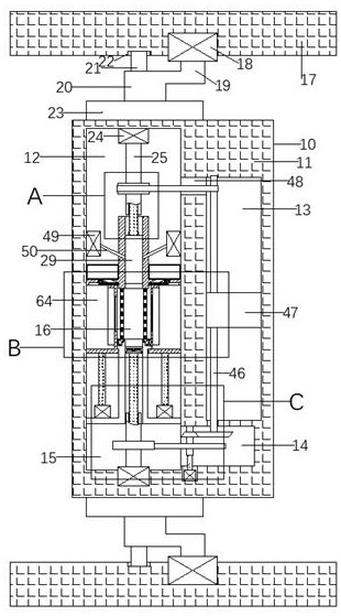
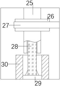
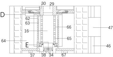
[0022] Combine below Figure 1-6 The present invention is described in detail, wherein, for the convenience of description, the orientations mentioned below are defined as follows: figure 1 The up, down, left, right, front and back directions of the projection relationship itself are the same.

[0023] The abrasive flow processing equipment for a cylindrical workpiece described in conjunction with accompanying drawings 1-6 includes an equipment assembly 10 and a working box 11 arranged in the equipment assembly 10, and the working box 11 is provided with a first An extruding working chamber 12 and a second extruding working chamber 15 located below the first extruding working chamber 12, fixedly arranged between the first extruding working chamber 12 and the second extruding working chamber 15 Grinding and polishing cavity 16 is arranged, and described grinding and polishing cavity 16 is fixedly provided with the motor board 51 that is arranged on the wall surface of describe...


PUM


Abstract

The invention discloses abrasive flow machining equipment for a cylinder-shaped workpiece. The abrasive flow machining equipment comprises an equipment assembly and a working box arranged in the equipment assembly, and the working box is internally provided with a first extrusion working cavity and a second extrusion working cavity arranged below the first extrusion working cavity. The abrasive flow machining equipment is mainly used for the cylinder-shaped workpiece, the effect that the inner wall and the outer wall of the cylinder-shaped workpiece are polished at the same time can be achieved through abrasive flow, after polishing is completed, the redundant abrasive flow is extruded into one cavity for secondary utilization, after the abrasive flow is extruded, a water pump is lifted tothe inner wall of the cylinder-shaped workpiece to flush the interior of the cylinder-shaped workpiece, and meanwhile part of water flows outside the outer side of the cylinder-shaped workpiece through a gap, meanwhile a whole polishing cavity shakes, the inner wall, the outer wall and the gap of the cylinder-shaped workpiece are effectively cleaned, and the problems that when abrasives are extruded out of a workpiece, part of the abrasives remain in the gap, the cylinder-shaped workpiece needs to be taken out to for removing of the abrasives, procedures are complex, meanwhile, traditional abrasive flow polishing cannot achieve simultaneous polishing of the inside and the outside, and the polishing efficiency is low are solved.

Description

technical field [0001] The invention relates to an abrasive flow processing equipment for a cylindrical workpiece, and mainly relates to the technical field of abrasive materials. Background technique [0002] Abrasive flow machining, referred to as AFM, technology is a newest machining method, which uses abrasive media (a flowable mixture mixed with abrasive grains) to flow under pressure through the surface of the workpiece to be processed for deburring, Remove flash and round corners to reduce the waviness and roughness of the workpiece surface and achieve the finish of precision machining. [0003] The AFM method is the best alternative processing method for workpieces that require complicated manual finishing or complex shapes, as well as parts that are difficult to process by other methods, but the common problem is that when processing workpieces with holes , when the abrasive is extruded inside the workpiece, part of the abrasive will remain in the gap, and the cyli...

Claims


Application Information

Patent Timeline
IPC IPC(8): B24B31/116B24B31/12B08B3/04
CPCB08B3/04B24B31/116B24B31/12
Inventor 路文文
Owner 福州晋安区格撕图科技有限公司
Learn More