Photovoltaic system with improved DC connections and method of making same

a photovoltaic and dc connection technology, applied in the direction of pv power plants, electrical apparatus construction details, electrical apparatus casings/cabinets/drawers, etc., can solve the problems of reducing the load, ac pv module overheating, and typical ac pv module making infield repairs time-consuming and labor-intensiv

Active Publication Date: 2015-04-16
GENERAL ELECTRIC CO
View PDF3 Cites 18 Cited by
  • Summary
  • Abstract
  • Description
  • Claims
  • Application Information

AI Technical Summary

Problems solved by technology

By removing AC PV module cells that are not producing DC power from the electrical connection, the PV system ensures that these non-producing AC PV module cells do not draw DC power from the PV system, which may reduce power to the load and cause AC PV module overheating.
The construction of typical AC PV modules makes infield repairs time consuming.
Further, the wired connection between the PV panel 304 and the micro-inverter typically includes approximately one to two feet of DC cable and a junction box, which adds cost to the PV system.
Further, installers must properly manage the safety risks posed by the potentially lethal DC voltages when dealing with installation of DC wiring.
Because all of the wiring is done on-site, the process for installing the DC wiring of the PV system accounts for a significant amount of the time and cost of the overall installation of the PV system.
Over the length of the AC wire harness 334, power is lost due to cable resistance, which results in lower efficiencies for PV systems with long wire harnesses.
This also results in a voltage drop along the length of the AC wire harness.
Further, resistance at each connection point along the length of the AC wire harness also results in power loss, and a decrease in efficiency for the PV system.

Method used


Image

  • Photovoltaic system with improved DC connections and method of making same
  • Photovoltaic system with improved DC connections and method of making same
  • Photovoltaic system with improved DC connections and method of making same

Examples


Embodiment Construction

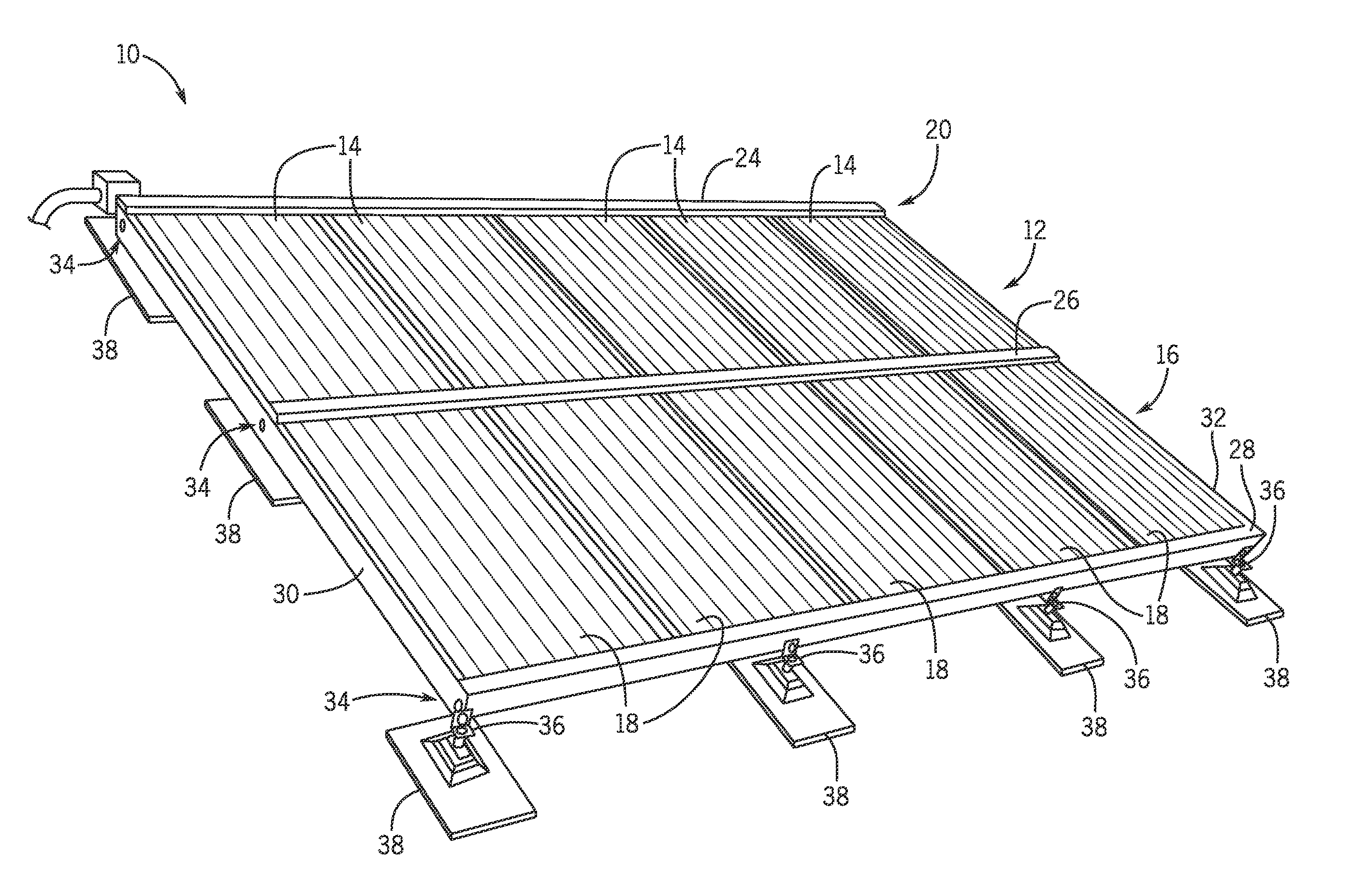
[0032]Referring now to FIG. 3, a PV system 10 is illustrated according to an embodiment of the invention. PV system 10 includes a first row 12 containing at least one AC PV module 14 and a second row 16 containing at least one AC PV module 18, and a rail system 20 that includes a number of support bars, as described in detail below. In the embodiment shown in FIG. 3, the first row 12 of PV system 10 includes five (5) AC PV modules 14, and the second row 16 of PV system 10 includes five (5) AC PV modules 18. However, one skilled it the art will appreciate that embodiments of the invention are not limited to rows 12, 16 having a particular number of AC PV modules 14, 18. Thus, according to alternative embodiments, rows 12, 16 may include any desirable number of AC PV modules 14, 18 depending on design specifications and applicable limitations imposed by the National Electrical Code (NEC). Further, PV system 10 may have more or less than two (2) rows of AC PV modules, according to alte...


PUM

PropertyMeasurementUnit
voltagesaaaaaaaaaa
rotationaaaaaaaaaa
adhesiveaaaaaaaaaa

Abstract

A micro-inverter assembly includes a housing having an opening formed in a bottom surface thereof, and a direct current (DC)-to-alternating current (AC) micro-inverter disposed within the housing at a position adjacent to the opening. The micro-inverter assembly further includes a micro-inverter DC connector electrically coupled to the DC-to-AC micro-inverter and positioned within the opening of the housing, the micro-inverter DC connector having a plurality of exposed electrical contacts.

Description

BACKGROUND OF THE INVENTION[0001]Embodiments of the invention relate generally to photovoltaic (PV) systems and more particularly to improved systems and methods for forming direct current (DC) electrical connections between a DC connector of a PV panel to a DC connector of a DC-to-alternating current (AC) micro-inverter and AC electrical connections between the micro-inverter and AC wiring harness of the PV system.[0002]PV systems include PV modules arranged in arrays that generate direct current (DC) power, with the level of DC current being dependent on solar irradiation and the level of DC voltage dependent on temperature. PV systems may be constructed either as an inverter system or a micro-inverter system. A typical inverter system uses DC wiring to electrically couple multiple PV panels to a single inverter. The inverter then converts the DC energy from the PV panels into AC energy, such as AC energy suitable for transfer to a power grid. A typical micro-inverter system, on t...

Claims


Application Information

Patent Timeline
Patent Type & Authority Applications(United States)
IPC IPC(8): H05K7/10H02S40/34H02M7/00H02S40/32
CPCH05K7/10H02S40/32H02S40/34H02M7/003H02S20/00Y02E10/50Y10T29/49117
Inventor CIOFFI, PHILIP MICHAELTODOROVIC, MAJA HARFMANHERZOG, MICHAEL SCOTTKORMAN, CHARLES STEVENDOHERTY, DONALD M.JOHNSON, NEIL ANTHONY
Owner GENERAL ELECTRIC CO
Why Eureka
Try Eureka