Thermal management system for vehicle

Active Publication Date: 2015-04-16
DENSO CORP
View PDF33 Cites 115 Cited by
  • Summary
  • Abstract
  • Description
  • Claims
  • Application Information

AI Technical Summary

Benefits of technology

The patent allows for the switching of coolants for two systems through a motor generator and inverter, but the battery, vehicle compartment, and reduction gear mechanism cannot be directly connected to the second circulation circuit, leading to limited flexibility in temperature adjustment. The technical effect is improved cooling flexibility for multiple systems.

Problems solved by technology

However, the battery, the vehicle compartment, and the reduction gear mechanism cannot be directly connected to the second circulation circuit, and thereby it is impossible to switch and circulate the coolants for two systems.
Accordingly, the battery, the vehicle compartment, and the reduction gear mechanism might have a low degree of flexibility in temperature adjustment.
This arrangement makes it difficult to exchange heat between a plurality of devices to be heat-exchanged so as to effectively use the heat.

Method used


Image

  • Thermal management system for vehicle
  • Thermal management system for vehicle
  • Thermal management system for vehicle

Examples


first embodiment

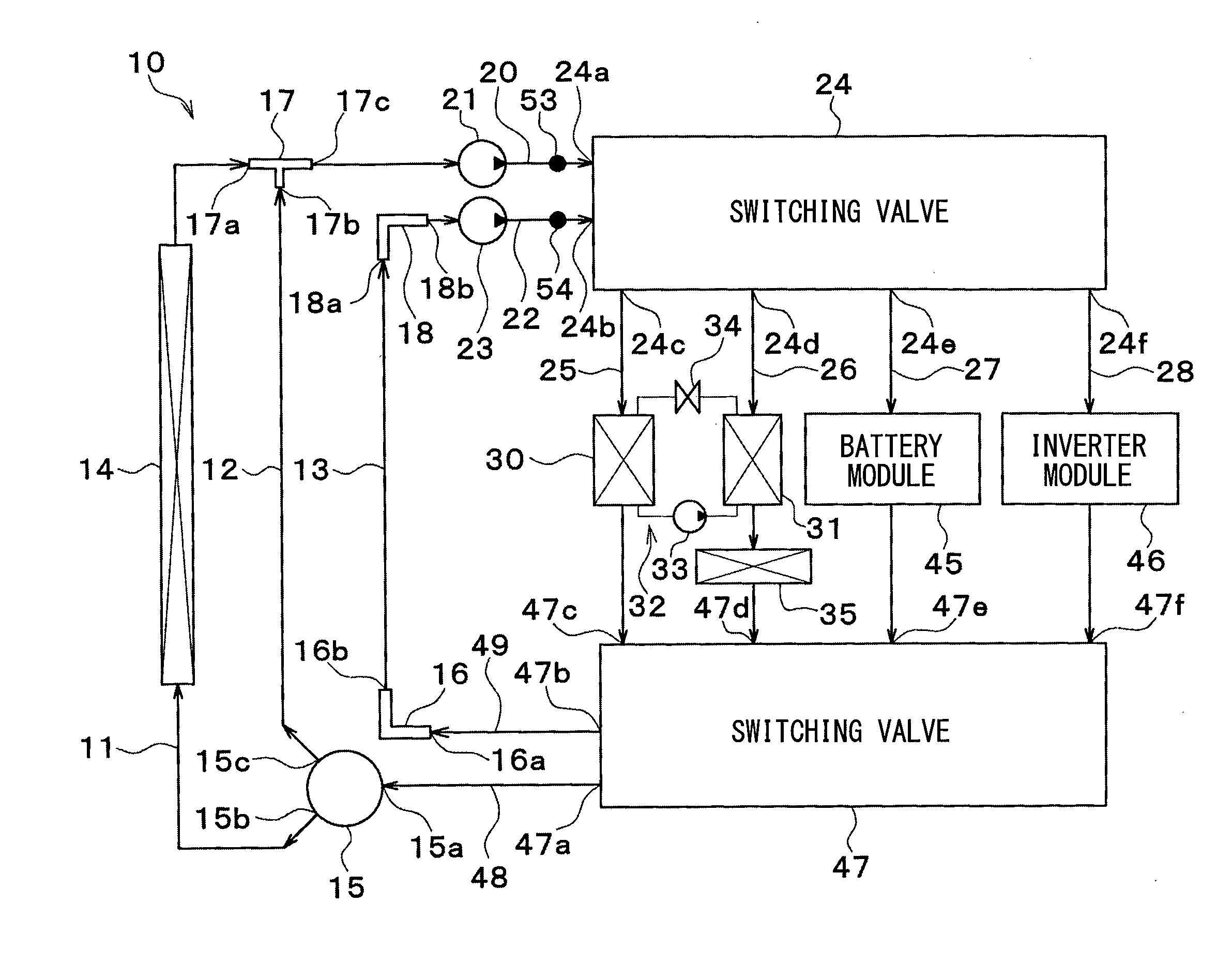
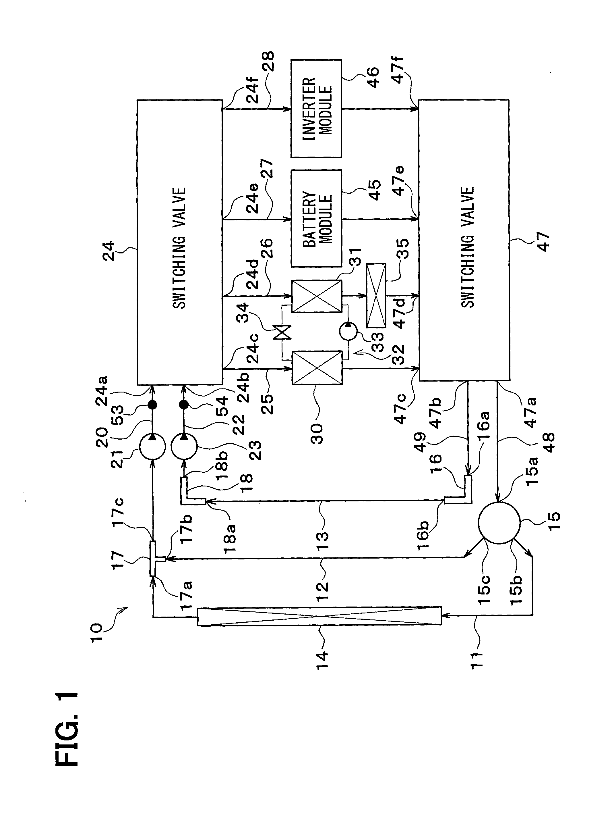
[0066]Now, a first embodiment of the invention will be described based on FIGS. 1 to 19. A vehicle thermal management system 10 shown in FIG. 1 is used to perform air conditioning (cooling or heating) of various devices mounted on a vehicle (devices requiring cooling or heating) or an interior of the vehicle to an appropriate temperature.

[0067]In this embodiment, the thermal management system 10 is applied to a hybrid vehicle that can obtain the driving force for traveling from both an internal combustion engine (engine) and an electric motor for traveling.

[0068]A hybrid vehicle of this embodiment is configured as a plug-in hybrid car that can charge a battery (vehicle-mounted battery) mounted on the vehicle with power supplied from an external power source (commercial power source) during stopping of the vehicle. For example, a lithium ion battery can be used as the battery.

[0069]A driving force output from an engine is used not only for traveling of the vehicle, but also for opera...

second embodiment

[0218]Although in the first embodiment, the battery module 45 directly exchanges heat between the battery 451 and the coolant, as shown in FIG. 20, in a second embodiment, a battery module 60 exchanges heat between the coolant and a battery 601 via the air.

[0219]The battery module 60 includes a casing 602 for accommodating therein the battery 601. The casing 602 forms an air passage through which the air blown by a blower 603 flows. The casing 602 is provided with an inside air introduction port 602a for introducing air in the vehicle interior (hereinafter referred to as an inside air).

[0220]The battery 601 is disposed on one end side of the inside of the casing 602. The inside air introduction port 602a is disposed on the other end side of the inside of the casing 602. One end part of the casing 602 with the battery 601 disposed therein is formed of thermal insulating material. Thus, the battery module 60 has a heat retaining structure for storing hot heat and cold heat in the batt...

third embodiment

[0258]In a third embodiment of the invention, as shown in FIG. 26, a coolant-refrigerant heat exchanger 61 is added to the structure of the above second embodiment.

[0259]The coolant-refrigerant heat exchanger 61 is a heat exchanger (heat medium-refrigerant heat exchanger) that exchanges heat between the coolant (heat medium) flowing from the battery heat exchanger 604 and the refrigerant flowing from the coolant-heating heat exchanger 31.

[0260]Specifically, the coolant-refrigerant heat exchanger 61 is disposed on the downstream side of the battery heat exchanger 604 in the third parallel flow path 27, and on the downstream side of the coolant-heating heat exchanger 31 in the refrigeration cycle 32. That is, the coolant-refrigerant heat exchanger 61 and the battery heat exchanger 604 are arranged in series in the third parallel flow path 27.

[0261]An electric expansion valve 62 is disposed between the coolant-heating heat exchanger 31 and the coolant-refrigerant heat exchanger 61. The...


PUM


Abstract

First circulation portions switch a flow of a heat medium such that one of the heat media for two systems selectively circulates through a radiator flow path or a first bypass flow path. Second circulation portions switch the flow of the heat medium such that the heat media for the two systems selectively circulate with respect to a second flow path group. The first circulation portions and the second circulation portions are adapted to switch the flow of the heat medium so as to form a first circulation circuit for allowing the heat medium to circulate among a first flow path group, the second flow path group, and a first pump, as well as a second circulation circuit for allowing the heat medium to circulate among the first flow path group, the second flow path group, and a second pump.

Description

CROSS REFERENCE TO RELATED APPLICATION[0001]The application is based on a Japanese Patent Applications No. 2012-118357 filed on May 24, 2012, and No. 2013-089455 filed on Apr. 22, 2013, the contents of which are incorporated herein by reference in its entirety.FIELD OF THE INVENTION[0002]The preset disclosure relates to a thermal management system used for a vehicle.BACKGROUND ART[0003]Conventionally, Patent Document 1 discloses a heat controller for a vehicle, which cools a motor generator and an inverter, and cools or heats a battery, a vehicle compartment, and a reduction gear mechanism.[0004]Heat controllers for vehicles include a cooling circuit for circulation of a coolant to cool the motor generator and the inverter, a first circulation circuit for circulation of a coolant to cool and heat the battery, vehicle compartment, and reduction gear mechanism, and a second circulation circuit for circulation of a coolant that passes through an exterior heat exchanger to exchange heat...

Claims


Application Information

Patent Timeline
IPC IPC(8): B60H1/00F01P7/16F01P3/20B60H1/06B60K11/02B60L50/16
CPCB60H1/00278B60H1/06B60K11/02F01P3/20F01P7/16F01P2050/24F01P2060/08B60H1/00899B60H2001/00928B60L1/003B60L1/02B60L2240/34B60L2240/445B60L2240/545B60K11/06B60K2001/003B60K2001/005B60K2001/0416Y02T10/70Y02T90/14B60H2001/00307B60H1/00485F01P7/165B60L2240/36B60L2240/525H01M10/625H01M10/6563H01M10/6561Y02T10/7072B60L53/14B60L50/16B60L50/51B60L58/26B60L58/27B60H1/32284Y02E60/10B60H2001/00961B60H1/039
Inventor ENOMOTO, NORIHIKOKAKEHASHI, NOBUHARUNISHIKAWA, MICHIOOMI, YASUMITSUYAMANAKA, TAKASHITAKEUCHI, MASAYUKI
Owner DENSO CORP
Why Eureka
Try Eureka