
Multi-Mode Portable Lighting Device

a lighting device and multi-mode technology, applied in the direction of electric lighting with batteries, semiconductor devices for light sources, lighting and heating apparatus, etc., can solve the problems of reducing the useful battery life of portable lighting devices with just a simple mechanical power switch, and not including automated operating modes

Active Publication Date: 2015-04-16
MAG INSTR INC
View PDF1 Cites 20 Cited by
  • Summary
  • Abstract
  • Description
  • Claims
  • Application Information

AI Technical Summary

Benefits of technology

This patent aims to offer a portable lighting device that uses a mechanical power switch and solves issues associated with previous multi-mode portable lighting devices. The technical effects of this patent are improved user experience and enhanced functionality of the portable lighting device.

Problems solved by technology

However, portable lighting devices having just a simple mechanical power switch do not include automated operating modes, such as, for example, a blink mode, a power reduction mode, or an SOS mode.
As a result, however, the electronics constantly consume power, thereby decreasing the useful battery life, or in the case of rechargeable batteries, the operational time between charges.
In the absence of the alternative source of temporary power, the microchip would lose power when the mechanical power switch is opened, causing the controller to reset and return to its default mode of operation the next time the mechanical power switch is closed instead of toggling to the next operational mode.

Method used


Image

  • Multi-Mode Portable Lighting Device
  • Multi-Mode Portable Lighting Device
  • Multi-Mode Portable Lighting Device

Examples


Embodiment Construction

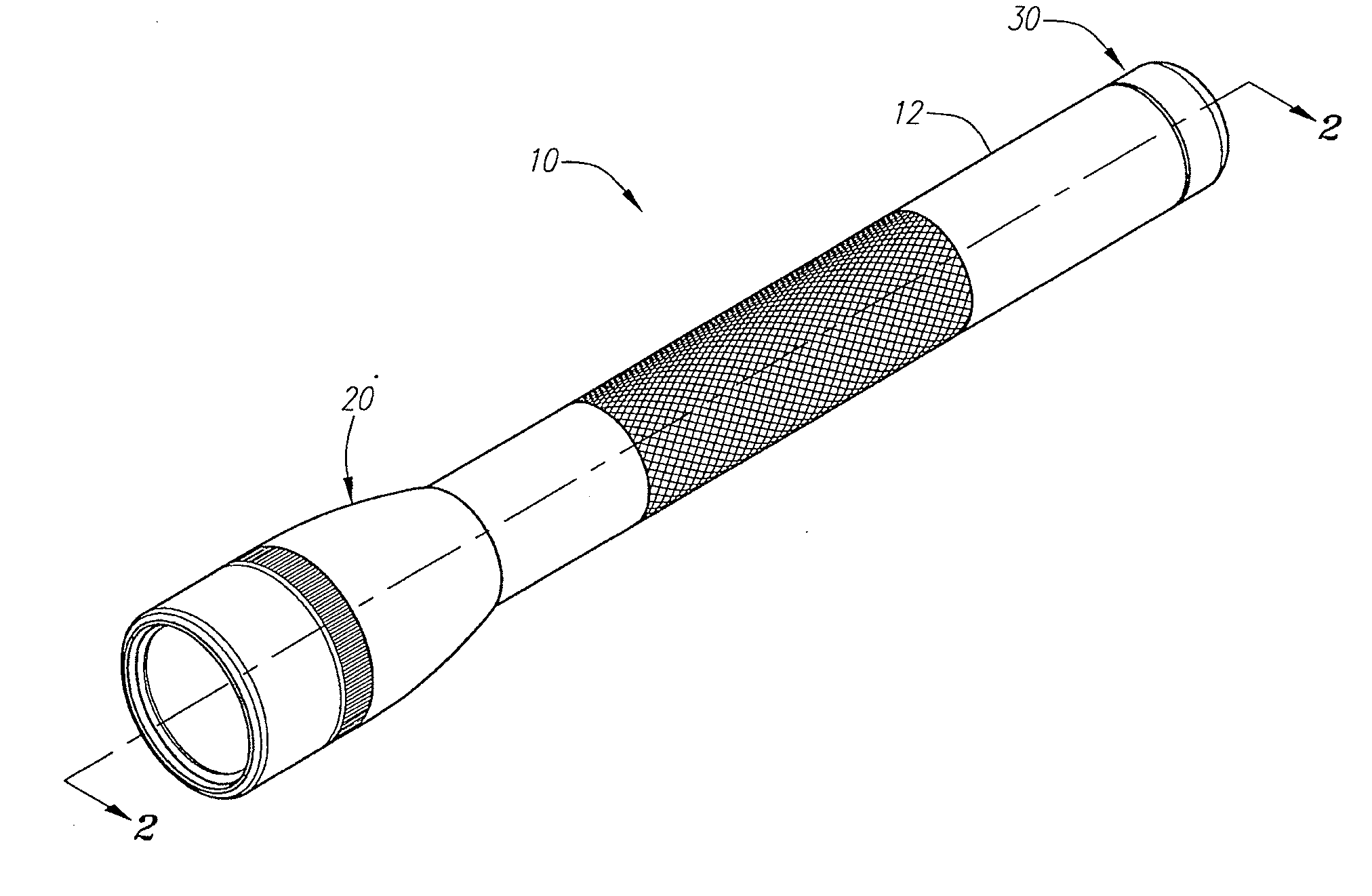
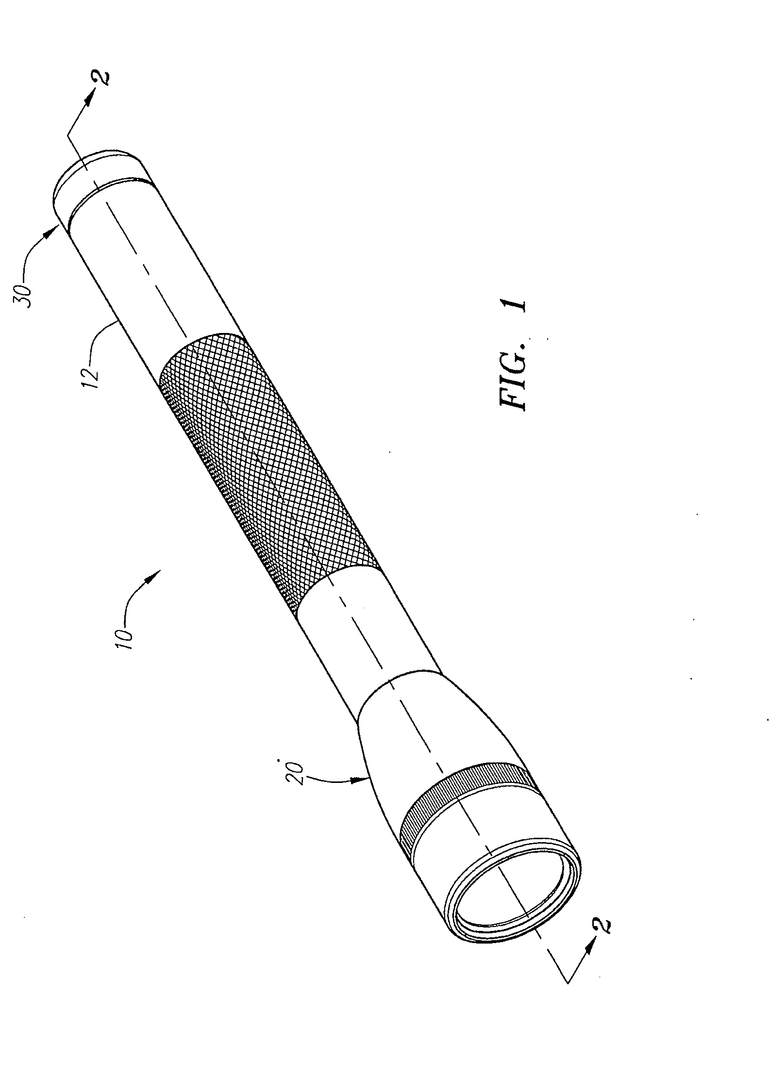
[0029]A multi-mode flashlight 10 according to an embodiment is illustrated in perspective in FIG. 1. The flashlight 10 incorporates a number of distinct aspects. While these distinct aspects have all been incorporated into the flashlight 10, it is to be expressly understood that the invention is not restricted to flashlight 10 described herein. Rather, the inventive features of the flashlight 10 described below, both individually as well as in combination, all form a part of the invention. Further, as will become apparent to those skilled in the art after reviewing the present disclosure, one or more aspects of the present invention may also be incorporated into other portable lighting devices, including, for example, head lamps and lanterns.

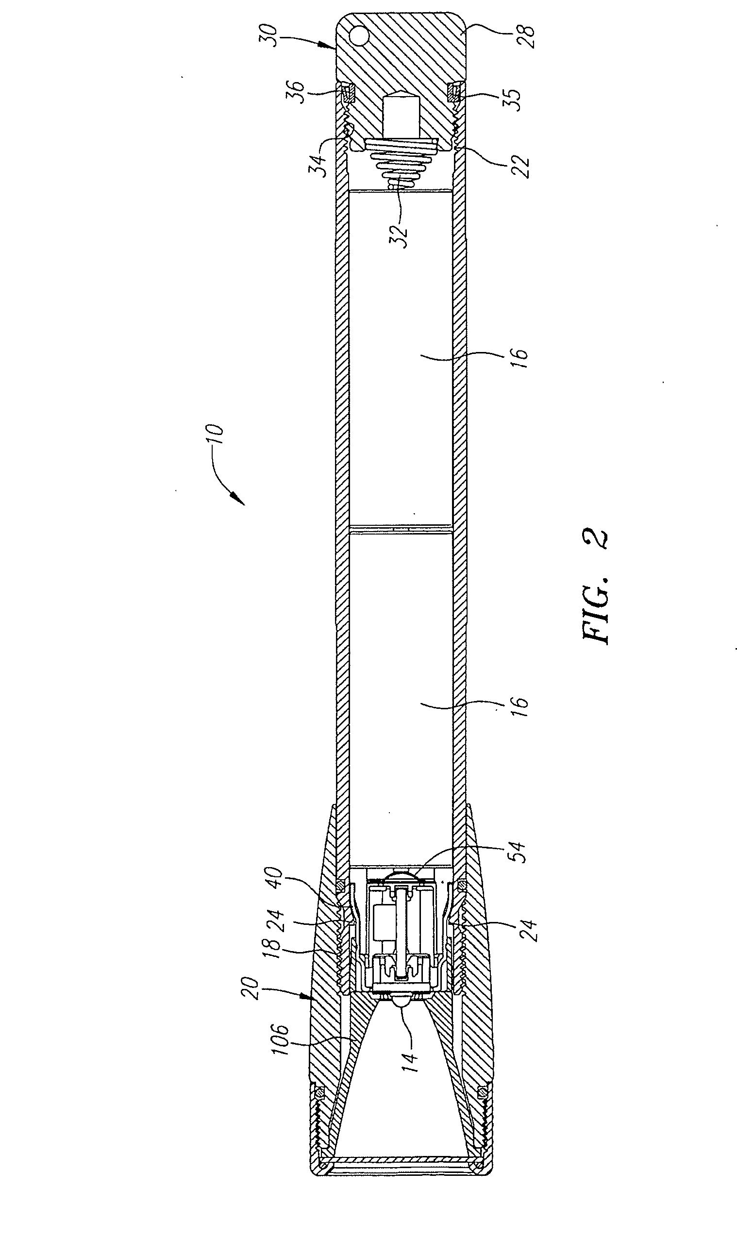
[0030]Referring to FIG. 1, the flashlight 10 includes a head assembly 20, a barrel 12, and a tail cap assembly 30. The head assembly 20 is disposed about the forward end of the barrel 12. The tail cap assembly 30 encloses the aft end of the barr...


PUM


Abstract

A portable lighting device, such as a flashlight, with a mechanical power switch and multiple operating modes is provided. The mechanical power switch is disposed in series with the controller for the lighting device and acts as the user interface to the controller to change modes of operation. Because the mechanical power switch is in series with the controller, the portable lighting device does not consume battery power when the mechanical switch is open. A state machine coupled to the controller is polled by the controller each time it is powered up to determine the operational mode of the lighting device. A regulating circuit is used to power a controller and light source. The regulating circuit converts between current regulation and voltage regulation.

Description

CROSS REFERENCE TO RELATED APPLICATIONS[0001]This is a continuation application of U.S. patent application Ser. No. 13 / 007,981, filed on Jan. 17, 2011, which is a continuation-in-part, and is based on and claims priority to U.S. patent application Ser. No. 12 / 353,396, filed Jan. 14, 2009, now U.S. Pat. No. 8,169,165, the disclosure of which is incorporated by reference as if fully set forth herein.TECHNICAL FIELD[0002]The present invention relates to portable lighting devices, including, for example, flashlights, lanterns and head lamps, and their circuitry.BACKGROUND[0003]Various handheld or portable lighting devices, including flashlights, are known in the art. Such lighting devices typically include one or more dry cell batteries having positive and negative electrodes. The batteries are arranged electrically in series or parallel in a battery compartment or housing. The battery compartment is also sometimes used to hold the lighting device, particularly in the case of flashlight...

Claims


Application Information

Patent Timeline
Patent Type & Authority Applications(United States)
IPC IPC(8): H05B33/08H05B37/02F21Y101/00H05B44/00
CPCH05B33/0815H05B37/02F21L4/027F21V23/0414F21Y2115/10Y02B20/30H05B45/325H05B45/38H05B45/375H05B47/17H05B45/3725
Inventor WEST, STACEY H.
Owner MAG INSTR INC
Learn More