Hinge assembly

a technology of hinges and parts, applied in the field of hinges, can solve the problems ofaffecting the service life of gates, and even removing, so as to achieve the effect of preventing and avoiding unauthorized removal of gates

Inactive Publication Date: 2015-04-23
TALPE JOSEPH
View PDF22 Cites 15 Cited by
  • Summary
  • Abstract
  • Description
  • Claims
  • Application Information

AI Technical Summary

Benefits of technology

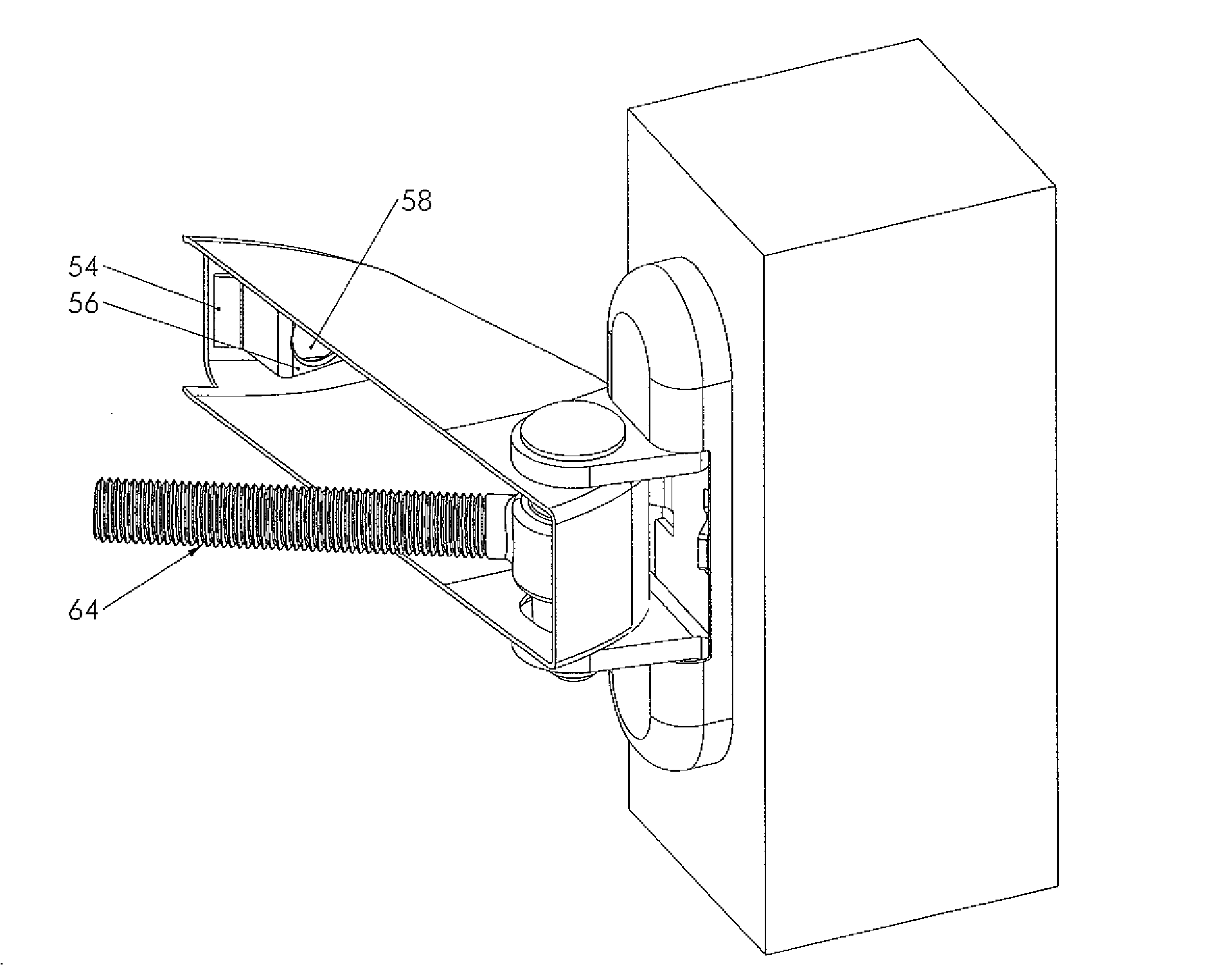
[0009]It is an aim of the present invention to provide a hinge assembly for mounting to parallel mounting surfaces of a support and gate which is more secure than known mechanisms and which can be adjusted without having to remove the hinge pin, i.e. without having to release the opening member from the support. In other words, an aim of the present invention is to provide a hinge assembly which enables to adjust the distance between the support and the opening member by means of the eye bolt after having mounted the opening member to the support and after having assembled the cover onto the hinge pin.

Problems solved by technology

A problem with such a mechanism is that at least part of the mechanism is exposed and can be tampered with, and even removed, when the gate is in a closed and locked position to allow access through the gate.
Although this is useful for certain types of gates, this is not useful in case of very thin gates, in cases where the material of the gate has less strength on the side, or in cases where a small gap is desired between support and gate.
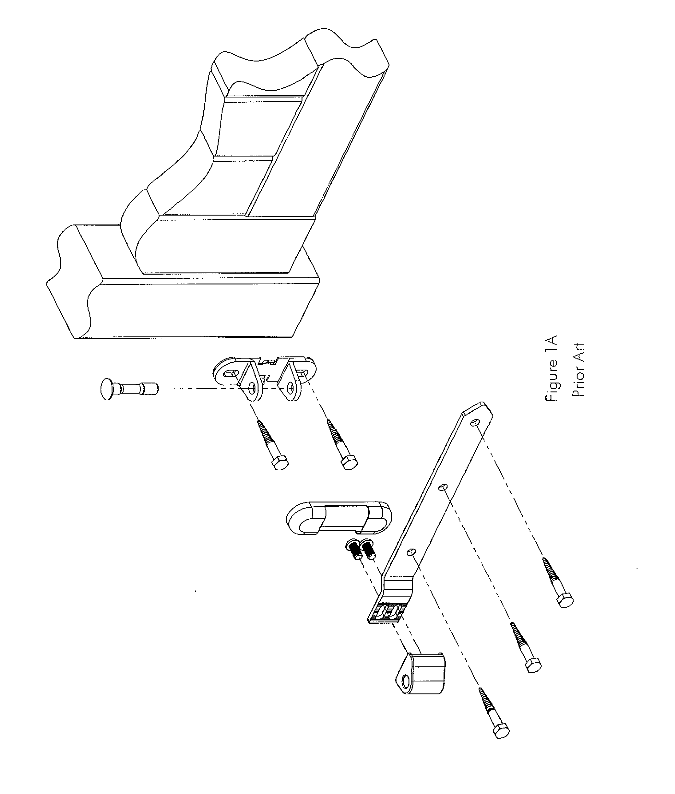
In the hinge assembly of FIG. 1A however someone could still access the screws connecting the hinge assembly to the gate such that unauthorized removal of the gate would still be possible.
A drawback of this known hinge assembly is that the distance between the support and the opening member cannot be adjusted without removing the cover from the hinge pin, i.e. without removing first the opening member from the support.

Method used


Image

  • Hinge assembly
  • Hinge assembly
  • Hinge assembly

Examples


Embodiment Construction

[0047]The present invention will be described with respect to particular embodiments and with reference to certain drawings but the invention is not limited thereto but only by the claims. The drawings described are only schematic and are non-limiting. In the drawings, the size of some of the elements may be exaggerated and not drawn on scale for illustrative purposes. The dimensions and the relative dimensions do not necessarily correspond to actual reductions to practice of the invention.

[0048]Furthermore, the terms first, second, third and the like in the description and in the claims, are used for distinguishing between similar elements and not necessarily for describing a sequential or chronological order. The terms are interchangeable under appropriate circumstances and the embodiments of the invention can operate in other sequences than described or illustrated herein.

[0049]Moreover, the terms top, bottom, over, under and the like in the description and the claims are used fo...


PUM

PropertyMeasurementUnit
axis of rotationaaaaaaaaaa
rotational movementaaaaaaaaaa
displacementaaaaaaaaaa

Abstract

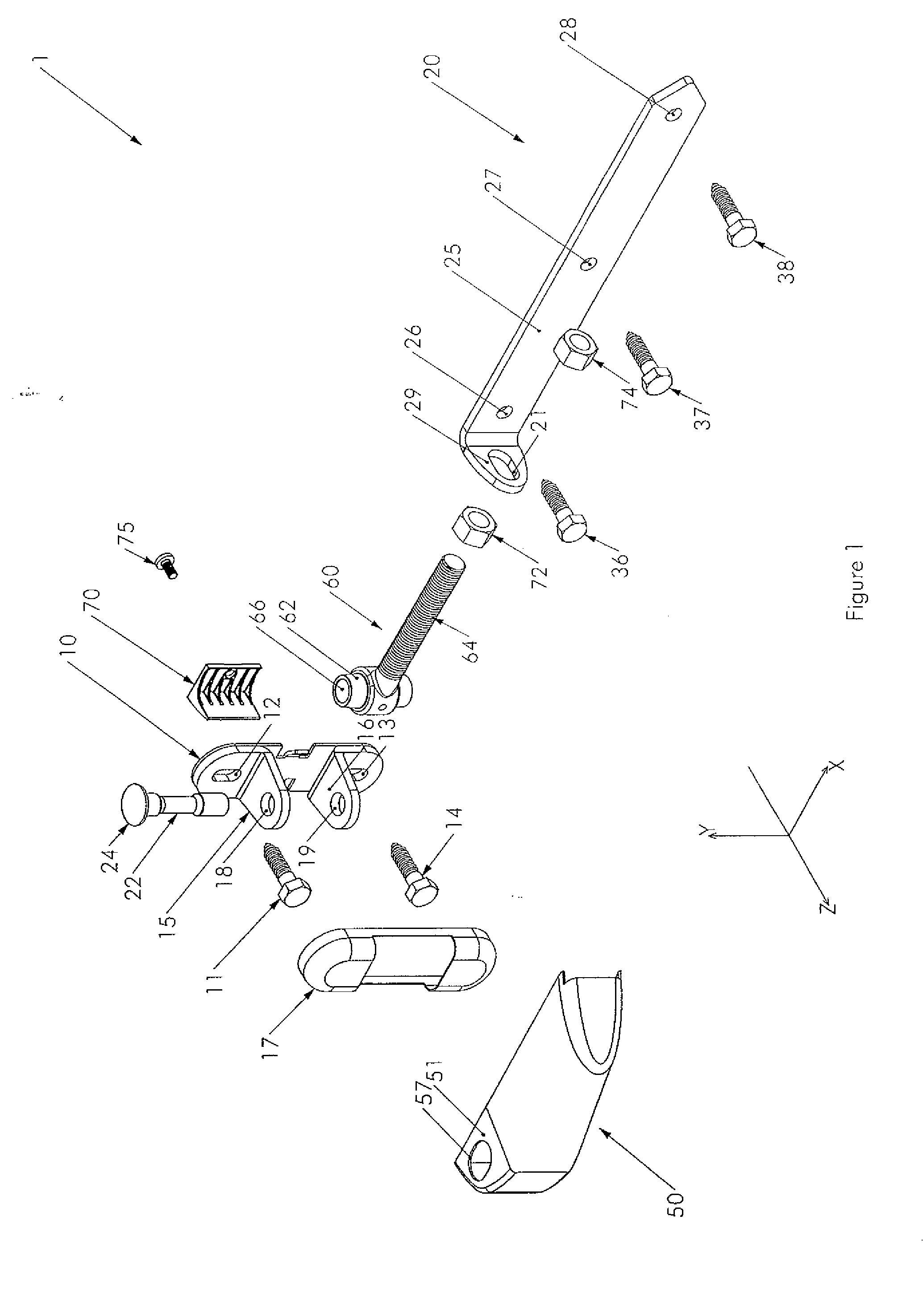
The hinge assembly for mounting on substantially parallel surfaces has an eye bolt including a threaded portion. A mounting member is positioned on the threaded portion of the eye bolt with two nut elements and connected to a gate by fixing means. The hinge assembly further has a mounting pin for connecting the eye bolt to the support. The hinge assembly has a securing cover mountable over the two nut elements and over at least a part of the fixing means of the mounting member connecting to the gate. The cover further has assembling means for assembling the cover to the eye bolt and the mounting pin still allowing displacement of the cover in the longitudinal direction of the eye bolt. The hinge assembly further has a cover support member for fixing the cover in the longitudinal direction preventing unauthorized dismounting of the gate.

Description

RELATED APPLICATIONS[0001]The present application claims priority to European Patent App. No. 13189425.5, filed on 18 Oct. 2013. The application referred to in this paragraph is incorporated by reference as if set forth fully herein.TECHNICAL FIELD[0002]The present invention relates to a hinge assembly for mounting on substantially parallel mounting surfaces and more specifically to a hinge assembly which secures against unauthorized dismounting.[0003]The present invention further relates to a method for adjustment of a hinge assembly which secures against unauthorized dismounting.BACKGROUND ART[0004]Hinge assemblies for mounting gates to a support are known. There is a large variety of hinge assemblies ranging from very simple assemblies where there is no adjustment and no prevention for dismounting to more complex assemblies that provide adjustment in three dimensions and prevent unauthorized dismounting.[0005]One such more complex hinge assembly with adjustment in three direction...

Claims


Application Information

Patent Timeline
Patent Type & Authority Applications(United States)
IPC IPC(8): E05D11/00E05D7/00E05D3/02
CPCE05D11/0018E05D11/0054E05D7/0045E05D3/02E05D7/0423E05D7/043E05Y2900/40Y10T29/24Y10T29/49721
Inventor TALPE, JOSEPH
Owner TALPE JOSEPH
Why Eureka
Try Eureka