
No grip cutter

a rotary cutter and no grip technology, applied in the field of hand tools, can solve the problems of difficult or even impossible for a large portion of the population to grasp an object in the manner, and the way the rotary cutter must be manipulated, and achieve the effects of simple operation, light weight and easy operation and maintenan

Inactive Publication Date: 2015-04-23
KOONTZ TERRY
View PDF17 Cites 5 Cited by
  • Summary
  • Abstract
  • Description
  • Claims
  • Application Information

AI Technical Summary

Benefits of technology

The present invention provides a no grip rotary cutter that is easy to operate, light weight, reliable, and inexpensive. The technical effects of this invention include improved efficiency, accuracy, and durability of the no grip rotary cutter.

Problems solved by technology

For a variety of reasons, quite often arthritis, many people have difficulty gripping an object in the manner prior art rotary cutters must be gripped.
That is, wrapping your hand around a cylinder and squeezing the way a rotary cutter must be manipulated, is very difficult or even impossible for a sizable portion of the population.

Method used


Image

  • No grip cutter
  • No grip cutter

Examples


Embodiment Construction

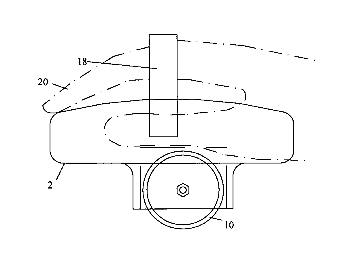
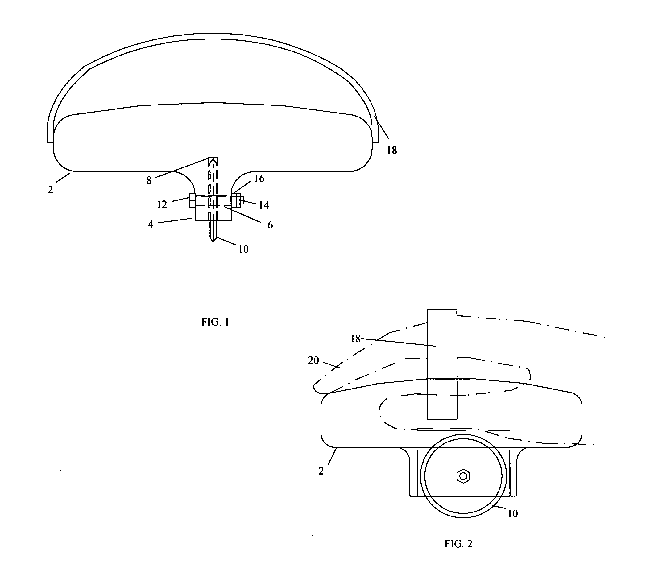
[0015]Referring to the drawings, FIGS. 1 and 2 there is shown a preferred embodiment of the instant invention. As with any conventional rotary cutter, the rotary cutter of the instant invention cut by pushing the cutter downward and forward. The direction of cutting travel is considered forward. The forward / rearward axis is considered the line of travel.

[0016]Now referring to FIG. 1, a front view of a no grip rotary cutter of the instant invention is shown. A block 2 is provided which is of appropriate size and shape to fit comfortably in the hand. A stud 4 protrudes downward from the base of the block 2. The stud 4 is longer in the direction of the line of travel than it is wide. Said stud 4 is slightly longer than the diameter of a conventional circular cutting blade. Said stud 4 is in the middle of the block 2 in the line of travel and slightly rearward of the centerline of said block 2 in a horizontal axis perpendicular to the line of travel. There is a hole 6 through said stud ...


PUM


Abstract

A no grip rotary cutter is disclosed which may be used to cut materials such as cloth by pushing on the cutter with the palm of the hand.

Description

BACKGROUND OF THE INVENTION[0001]1. Field of the Invention:[0002]The present invention relates generally to hand tools and more specifically to a no grip rotary cutter which may be used to cut a variety of items including cloth.[0003]2. Background Information:[0004]Throughout history, people have struggled to find tools which may be used to cut various materials. For many years the rotary cutter has been used to cut materials such as cloth, paper, or even pizza.[0005]The patent to Melter (U.S. Pat. No. 5,101,564; Apr. 7, 1992) discloses a rotary cutter which is very typical of the known configurations of such cutters. This patent provides a good history of patents issued in this field and notes the early Curtis patent (U.S. Pat. No. 278,103; May 22, 1883). The patent also includes a good general descriptions of these cutters “. . . an elongate handle with a circular cutting blade rotatably fastened to one end. The user grasps the handle and rolls the circular cutting blade along the...

Claims


Application Information

Patent Timeline
Patent Type & Authority Applications(United States)
IPC IPC(8): B26B25/00
CPCB26B25/005
Inventor KOONTZ, TERRY
Owner KOONTZ TERRY
Learn More