
Payload ejection system

Inactive Publication Date: 2006-05-11
AIRPORTS AUTHORITY OF INDIA
View PDF40 Cites 8 Cited by
  • Summary
  • Abstract
  • Description
  • Claims
  • Application Information

AI Technical Summary

Benefits of technology

[0003] A more simple and light weight payload ejection system is desirable from both reliability and cost standpoints.

Problems solved by technology

Servos, electric motors, pneumatic pistons and solenoids are relatively heavy and often rely on a complex mechanical system of levers to release and eject the payload.

Method used


Image

  • Payload ejection system
  • Payload ejection system
  • Payload ejection system

Examples


Embodiment Construction

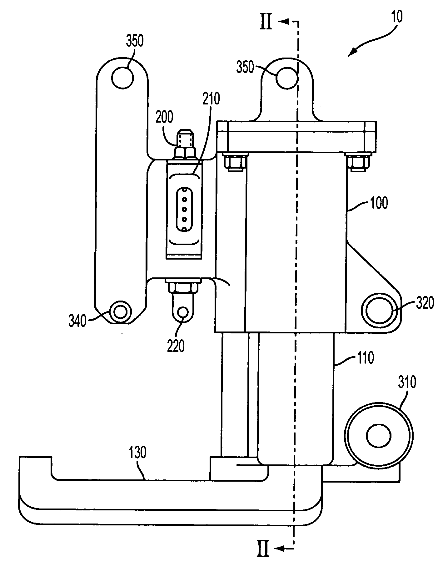
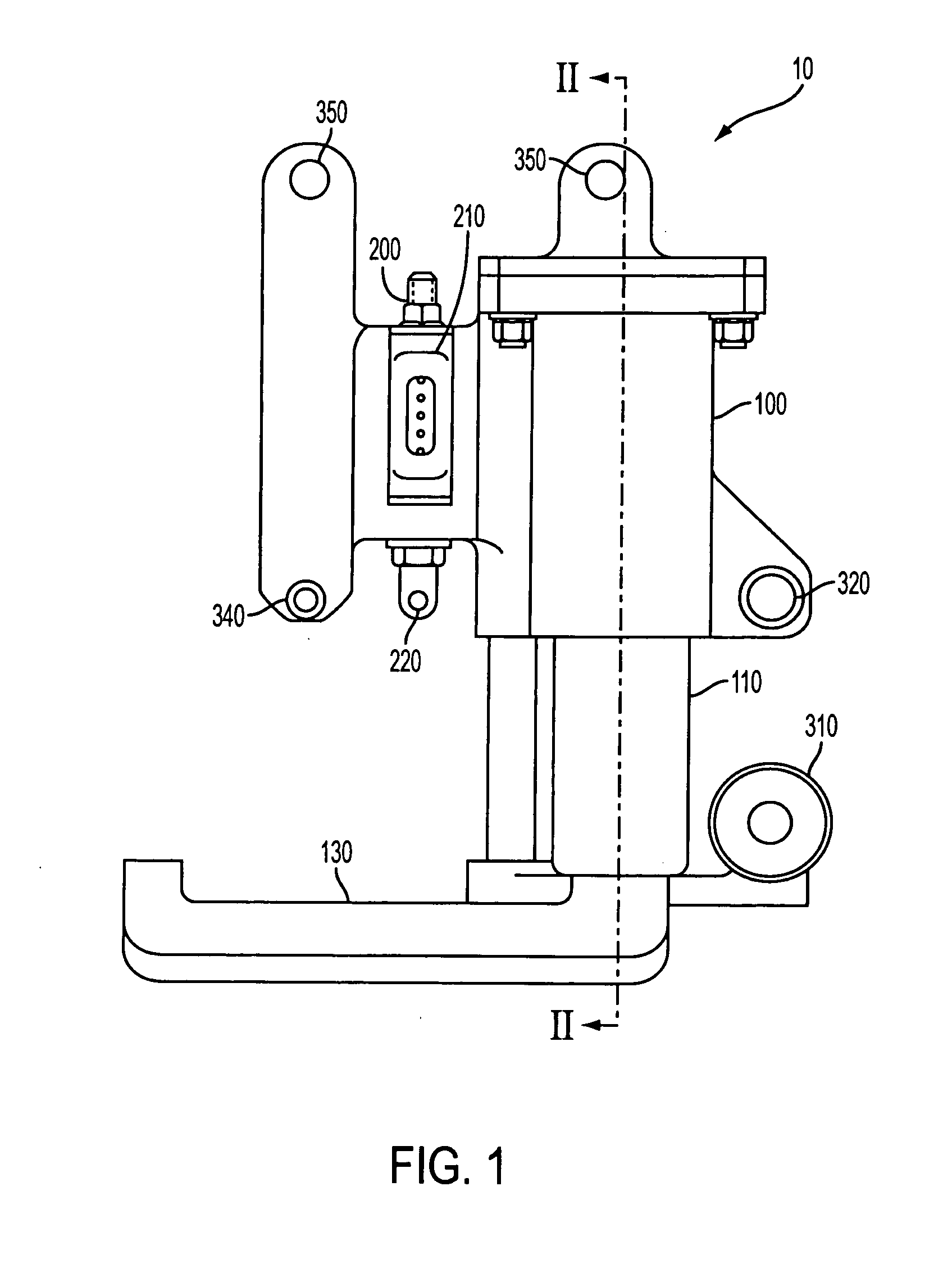
[0014] The invention will be described using the example of a payload ejection system mounted to an aircraft. The invention provides a payload ejection system that overcomes many of the problems associated with payload ejection systems currently in use. The system has two main components, an ejector mechanism and a payload release mechanism.

[0015] The ejector mechanism provides self-contained stored energy for ejecting the payload away from the aircraft carrying the payload. The payload release mechanism releases the energy stored in the ejector mechanism upon receiving a launch signal.

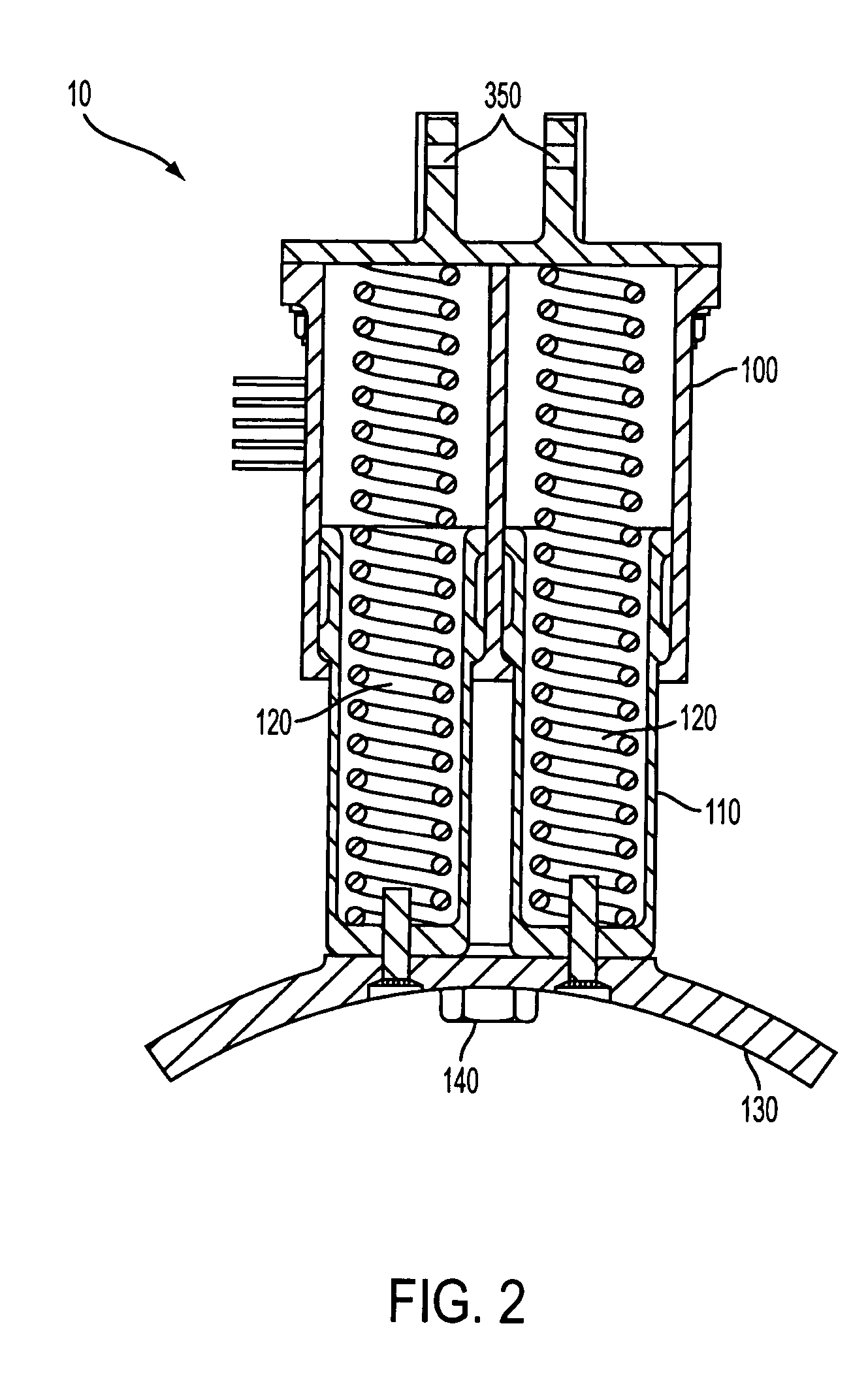
[0016] In the example shown in the drawings, the ejector mechanism uses two springs to store the energy needed to eject the payload from the aircraft. By using compressed springs, no ejector mechanism energy source (such as, for example, compressed air cylinders) is needed on the aircraft.

[0017] The payload release mechanism uses an actuator that fractures a payload mounting bolt so as to release t...


PUM


Abstract

A payload ejection system is provided for ejecting a payload from a transport vehicle. The system has an ejector mechanism for applying an ejection force to the payload to urge the payload away from the transport vehicle, and a release mechanism for releasing the payload from a restrained state. The release mechanism has a payload mounting bolt for holding the payload in the restrained state, and an actuator that fractures the mounting bolt. The actuator has a shape memory alloy, and an activator that transforms the shape memory alloy from a compressed state to an elongated state. The actuator fractures the mounting bolt as the shape memory alloy transforms into the elongated shape.

Description

BACKGROUND OF THE INVENTION [0001] The invention relates to release mechanisms, more particularly to payload release mechanisms. [0002] Known aircraft payload release mechanisms for bombs, missiles and other expendable stores release the payload using pyrotechnic bolts, servos, pneumatic pistons, electric motors or solenoids. Servos, electric motors, pneumatic pistons and solenoids are relatively heavy and often rely on a complex mechanical system of levers to release and eject the payload. Pyrotechnic bolts require a secondary mechanism to push the payload away from the aircraft. Such secondary mechanisms often include pneumatic pistons that require a high pressure supply tank on the aircraft. SUMMARY OF THE INVENTION [0003] A more simple and light weight payload ejection system is desirable from both reliability and cost standpoints. [0004] An embodiment of the invention provides a payload ejection system for ejecting a payload from a transport vehicle. The system has an ejector m...

Claims


Application Information

Patent Timeline
IPC IPC(8): B64D1/12
CPCB64D1/02B64G1/645
Inventor LANDSBERG, GARY BRYAN
Owner AIRPORTS AUTHORITY OF INDIA
Learn More