Display device and drive method therefor

Active Publication Date: 2015-04-23
SHARP KK
View PDF2 Cites 0 Cited by
  • Summary
  • Abstract
  • Description
  • Claims
  • Application Information

AI Technical Summary

Benefits of technology

The present invention provides a display device that can pause and does not have image sticking on the display panel, which is beneficial.

Problems solved by technology

The liquid crystal display device has a problem of having image sticking on a display panel when DC driven.
On the other hand, in recent years, display devices of various kinds share a common issue of how to reduce power consumption.

Method used


Image

  • Display device and drive method therefor
  • Display device and drive method therefor
  • Display device and drive method therefor

Examples


first embodiment

[0022](Arrangement of Display System 1)

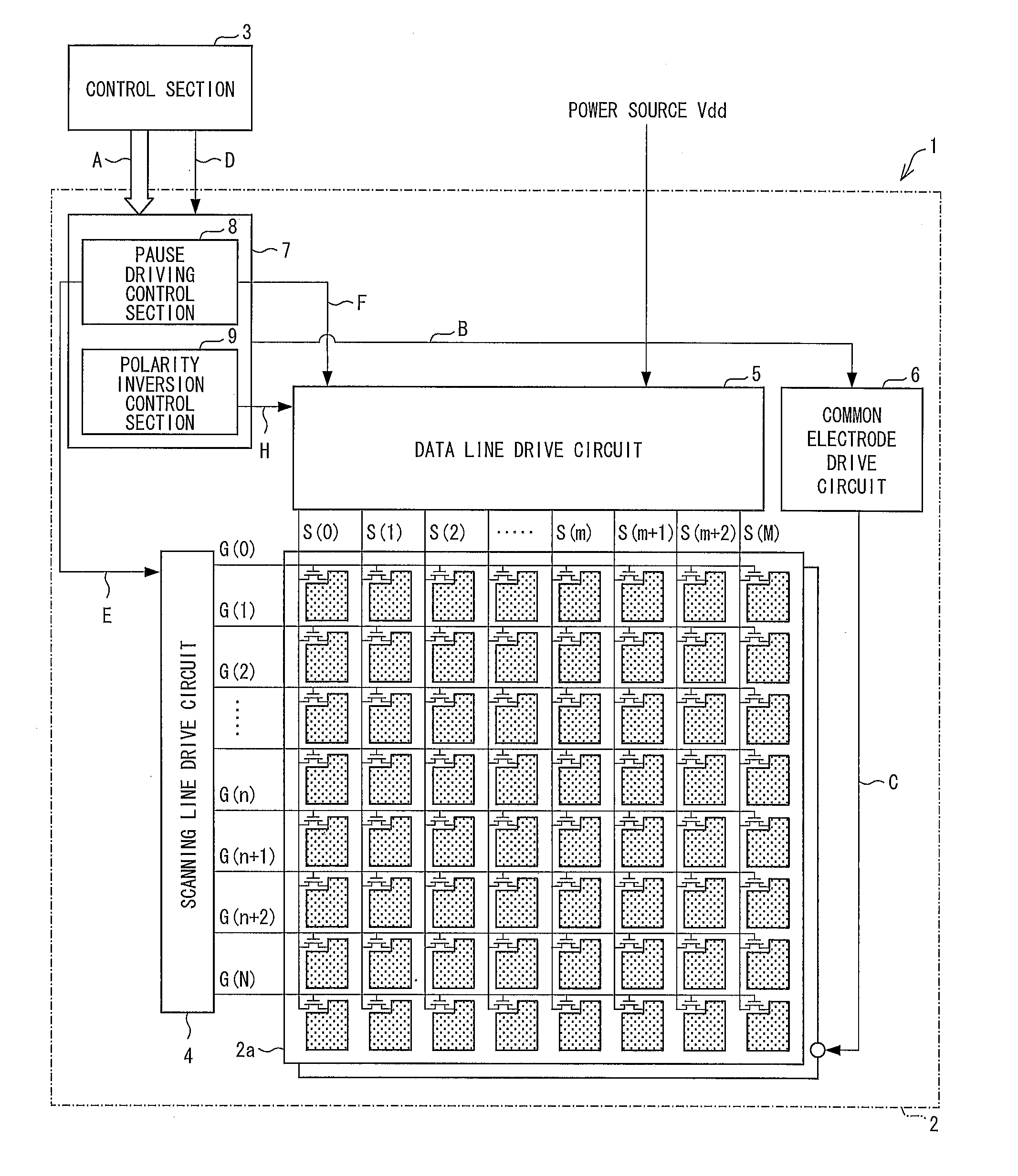
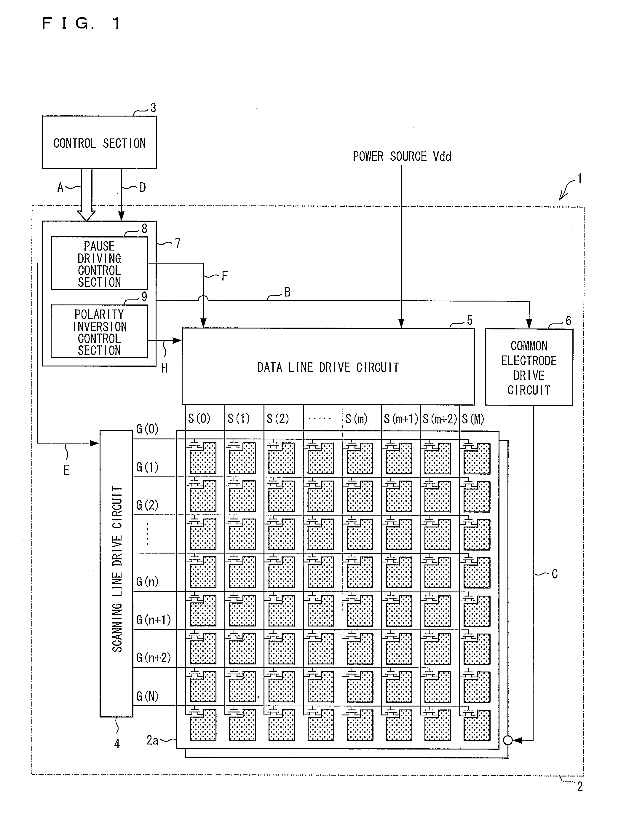
[0023]The following description will discuss, with reference to FIG. 1, an arrangement of a display system 1 in accordance with the present embodiment. FIG. 1 is a block diagram illustrating details of an arrangement of the display system 1 in accordance with the present embodiment. As illustrated in FIG. 1, the display system 1 includes a display device 2 and a control section 3. In the display system 1 of the present embodiment, the control section 3 outputs video via the display device 2 so that the video is displayed. Apart from video, the control section 3 is also capable of outputting, to the display device 2, given information such as a static image or a sign.

[0024]The display device 2 includes a display panel 2a, a scanning line drive circuit 4, a data line drive circuit 5 (a drive circuit), a common electrode drive circuit 6, and a timing control section 7. The timing control section 7 includes a pause driving control section 8 (a cont...


PUM


Abstract

A polarity of a POL outputted from a polarity inversion control section (9) is always identical between a scanning period and a pause period immediately subsequent to the scanning period, and is reversed every time switching from a pause period to a scanning period is carried out. This makes it possible to both carry out pause driving and prevent image sticking on a display panel.

Description

TECHNICAL FIELD[0001]The present invention relates to a display device which carries out reverse polarity driving, and a method for driving the display device.BACKGROUND ART[0002]Conventionally, a liquid crystal display device has been mounted in a wide variety of electronic devices. Due to having advantages such as small thickness, light weight, and low power consumption, the liquid crystal display device is expected to be utilized further in the future.[0003]The liquid crystal display device has a problem of having image sticking on a display panel when DC driven. In general, in order to prevent the image sticking, the liquid crystal display device is driven by means of reverse polarity driving. According to the reverse polarity driving, a polarity of image data (data signal) written into each pixel constituting the display panel is reversed every frame. This causes a polarity of a voltage applied to liquid crystal in the each pixel to be reversed every frame as well, so that a po...

Claims


Application Information

Patent Timeline
IPC IPC(8): G09G3/36
CPCG09G3/3614G09G2310/061G09G2300/0823G09G3/3688G09G3/3648G09G2310/08G09G2320/0204G09G2320/046G09G2330/021
Inventor FUJIOKA, AKIZUMITAKAHASHI, KAZUKINAKANO, TAKETOSHIYANAGI, TOSHIHIROSHIBATA, YOSHINORI
Owner SHARP KK
Why Eureka
Try Eureka