Method and apparatus for synchronous rectifier operation

Active Publication Date: 2015-11-05
SEMICON COMPONENTS IND LLC
View PDF2 Cites 24 Cited by
  • Summary
  • Abstract
  • Description
  • Claims
  • Application Information

AI Technical Summary

Benefits of technology

The present patent relates to a method and apparatus for controlling a synchronous rectifier in a switched mode power supply circuit. The method includes sensing a current sense signal, comparing it to a RESET threshold, and commencing a minimum off time timer when the current sense signal exceeds the RESET threshold. The apparatus includes a comparator that compares the current sense signal to a RESET threshold and provides an output that is asserted when the current sense signal is above the RESET threshold and de-asserted otherwise. The technical effect of this patent is to improve the efficiency and synchronization of switched mode power supply circuits by minimizing noise and false triggering events caused by switching transients.

Problems solved by technology

The voltage drop across a diode, however, is a source of loss.
However, noise resulting from switching transients can result in false triggering of the switching transistor, leading to inefficient operation.
A problem still remains, though, after turn on, or after enabling the synchronous controller, since those events can occur just prior to the occurrence of a transient, which can be falsely detected as a proper triggering event and rectifier control will not be properly synchronized.
However, in conventional systems that use time blanking, synchronization errors can still occur, for example, after start up, when errant transients can otherwise falsely trigger blanking timers.

Method used


Image

  • Method and apparatus for synchronous rectifier operation
  • Method and apparatus for synchronous rectifier operation
  • Method and apparatus for synchronous rectifier operation

Examples


Embodiment Construction

[0015]Embodiments disclosed herein include a method for self-synchronization in a synchronous rectifier controller (SRC). The method includes sensing a current sense signal, comparing the current sense signal to a RESET threshold, commencing a minimum off time timer when the current sense signal exceeds the RESET threshold, and resetting the minimum off time timer when the current sense voltage falls below the RESET threshold before the minimum off time timer has lapsed.

[0016]Embodiments also include a SRC that includes a RESET comparator that compares a current sense signal to a RESET threshold and provides an output that is asserted when the current sense signal is above the RESET threshold and de-asserted otherwise. The SRC can also include a minimum off time timer, and control logic that commences the minimum off time timer when the output of the RESET comparator is asserted and resets the minimum off time timer when output of the RESET comparator is de-asserted.
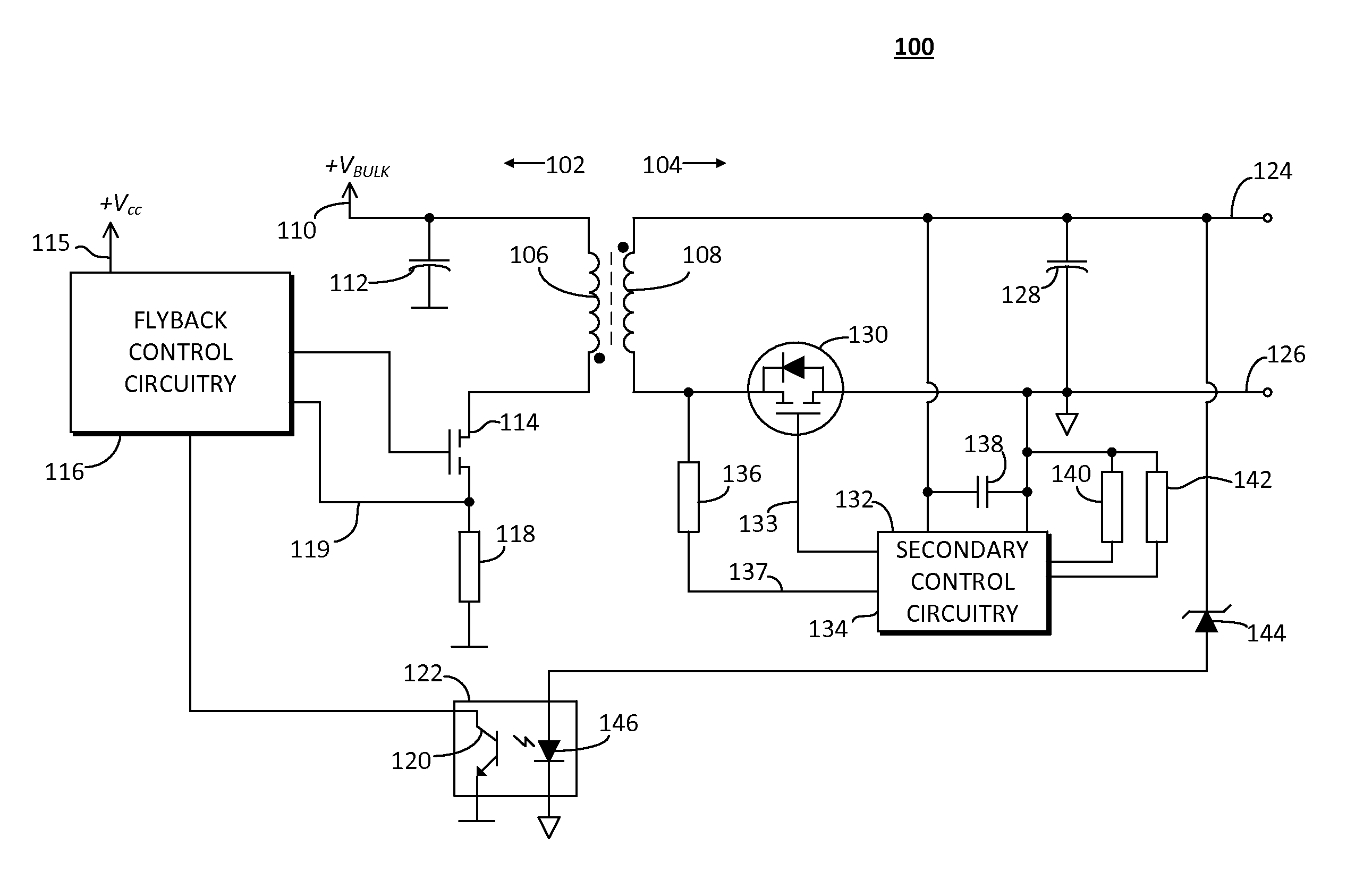
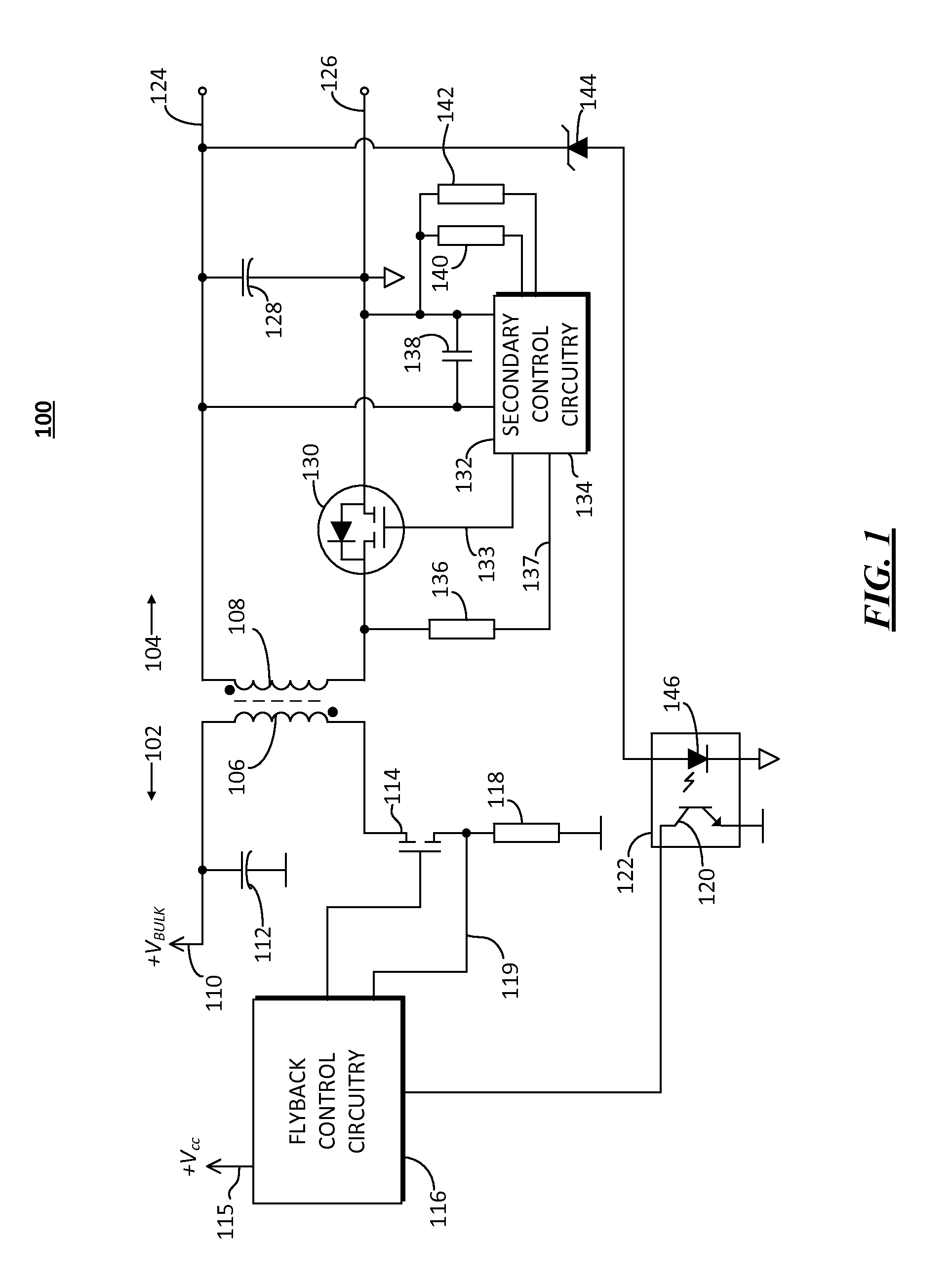
[0017]FIG. 1 is ...


PUM


Abstract

A method and synchronous rectifier controller uses minimum off and on time blanking to avoid switching the switching transistor at incorrect times responsive to transients in the current sense signal. The minimum off time timer is commenced only when the current sense signal is above a reset threshold, and is reset when the current sense voltage falls below the reset threshold. Resetting the minimum off time timer in this manner avoids false starts of the minimum off time timer due to transients and allows the SRC to properly synchronize with the conduction and blocking phases of rectifier operation.

Description

FIELD OF THE DISCLOSURE[0001]The present disclosure relates generally to switched mode power supply circuits, and more particularly to switched mode power supplies that use synchronous rectifiers and minimum blanking times to prevent triggering on noise components of a monitored signal.BACKGROUND[0002]Switched mode power supplies are widely used in a variety of applications due to their efficiency over alternative electric power regulators such as linear regulators. One technique for increasing the efficiency of a switched mode power supply (SMPS) is synchronous rectification. Rectifiers (e.g. diodes) are conventionally used on the secondary side to convert the alternating current (AC) waveform propagated through the transformer in a direct current (DC) at a regulated level, either voltage or current. The voltage drop across a diode, however, is a source of loss.[0003]To reduce the loss due to rectification a switching transistor such as a metallic oxide semiconductor field effect t...

Claims


Application Information

Patent Timeline
IPC IPC(8): H02M3/335
CPCH02M3/33592H02M1/0038Y02B70/10H02M3/335H02M3/33576
Inventor TICHY, TOMASPTACEK, KAREL
Owner SEMICON COMPONENTS IND LLC
Why Eureka
Try Eureka