Photoluminescent illuminators for passive illumination of sights and other devices

a technology of illuminating devices and illuminating spheres, which is applied in the field of photoluminescent illuminating devices, can solve problems such as compromising the ability of the device to be illuminated passively

Active Publication Date: 2015-04-23
DEFENSE HLDG
View PDF13 Cites 165 Cited by
  • Summary
  • Abstract
  • Description
  • Claims
  • Application Information

AI Technical Summary

Benefits of technology

[0007]According to one embodiment of the invention, there is provided a method for locating an object in a low ambient light environment using a photoluminescent illuminator. This method transmits external light into t

Problems solved by technology

In low light conditions, this capability is compromised especially by the u

Method used


Image

  • Photoluminescent illuminators for passive illumination of sights and other devices
  • Photoluminescent illuminators for passive illumination of sights and other devices
  • Photoluminescent illuminators for passive illumination of sights and other devices

Examples


Embodiment Construction

[0023]For the purpose of this invention, the term “passively charged” refers to the charging of non-radioactive photoluminescent materials by exposure to natural or artificial light sources. An example of passively charging a photoluminescent material using natural or artificial light is described below.

[0024]For the purposes of this invention, the term “photoluminescent material” refers to any item exhibiting photoluminescent characteristics.

[0025]For the purposes of this invention, the term “photoluminescent characteristics” refers to an item's ability to absorb light and later emit light, such as for example, during low light or darkened conditions.

[0026]For the purposes of this invention, the term “low ambient light environment: refers to nighttime, dusk, dawn, or conditions where natural or artificial illumination such as from powered light sources are not present.

[0027]For the purposes of this invention, the term “phosphors” refers to any material, especially in powder, granul...


PUM


Abstract

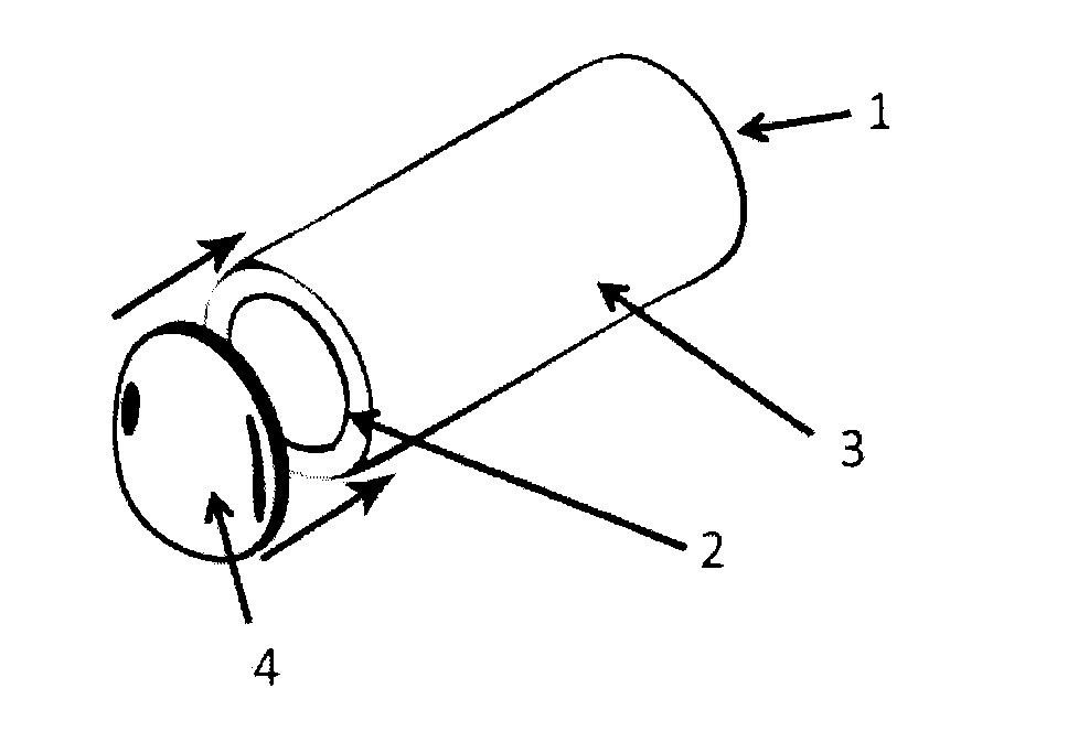
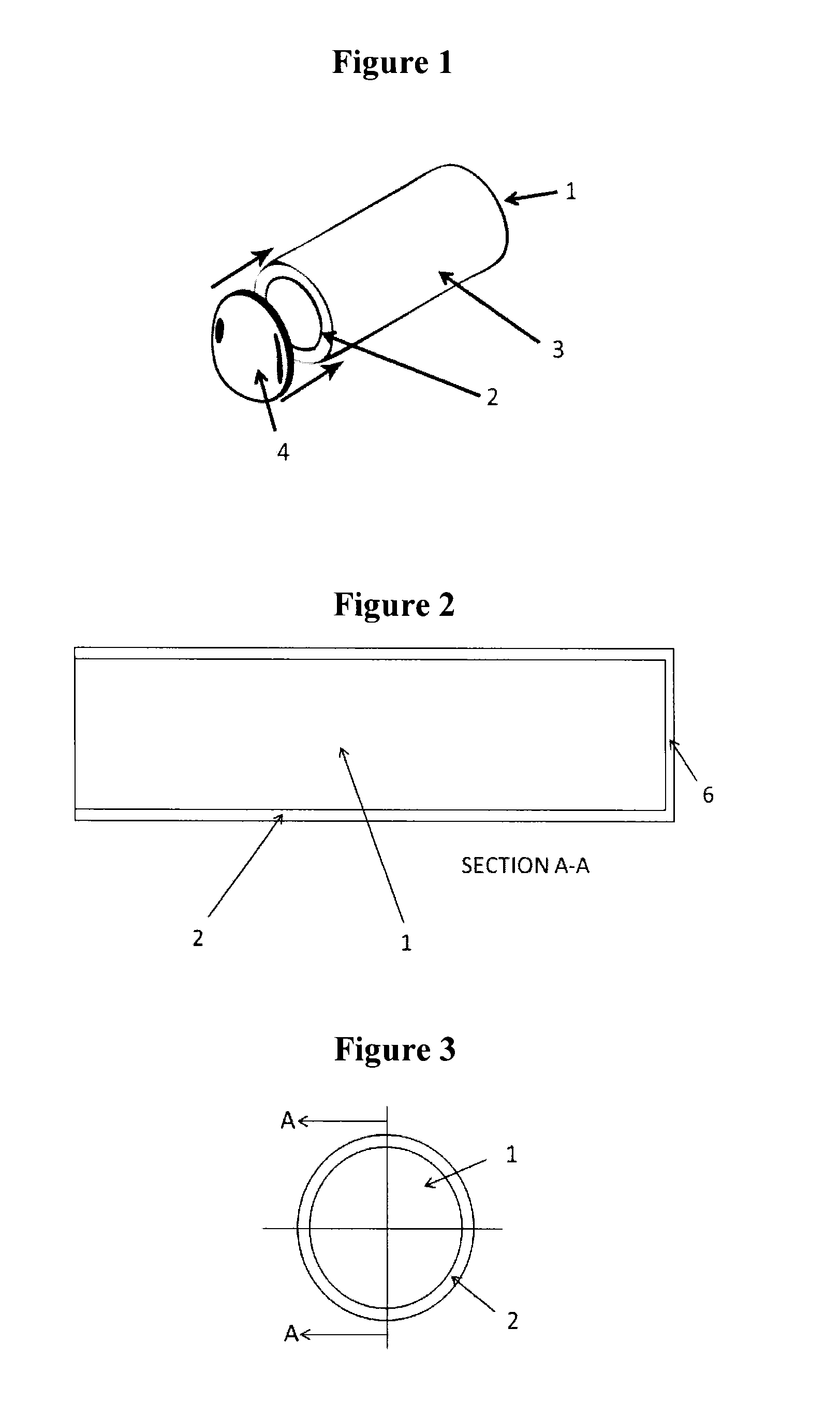
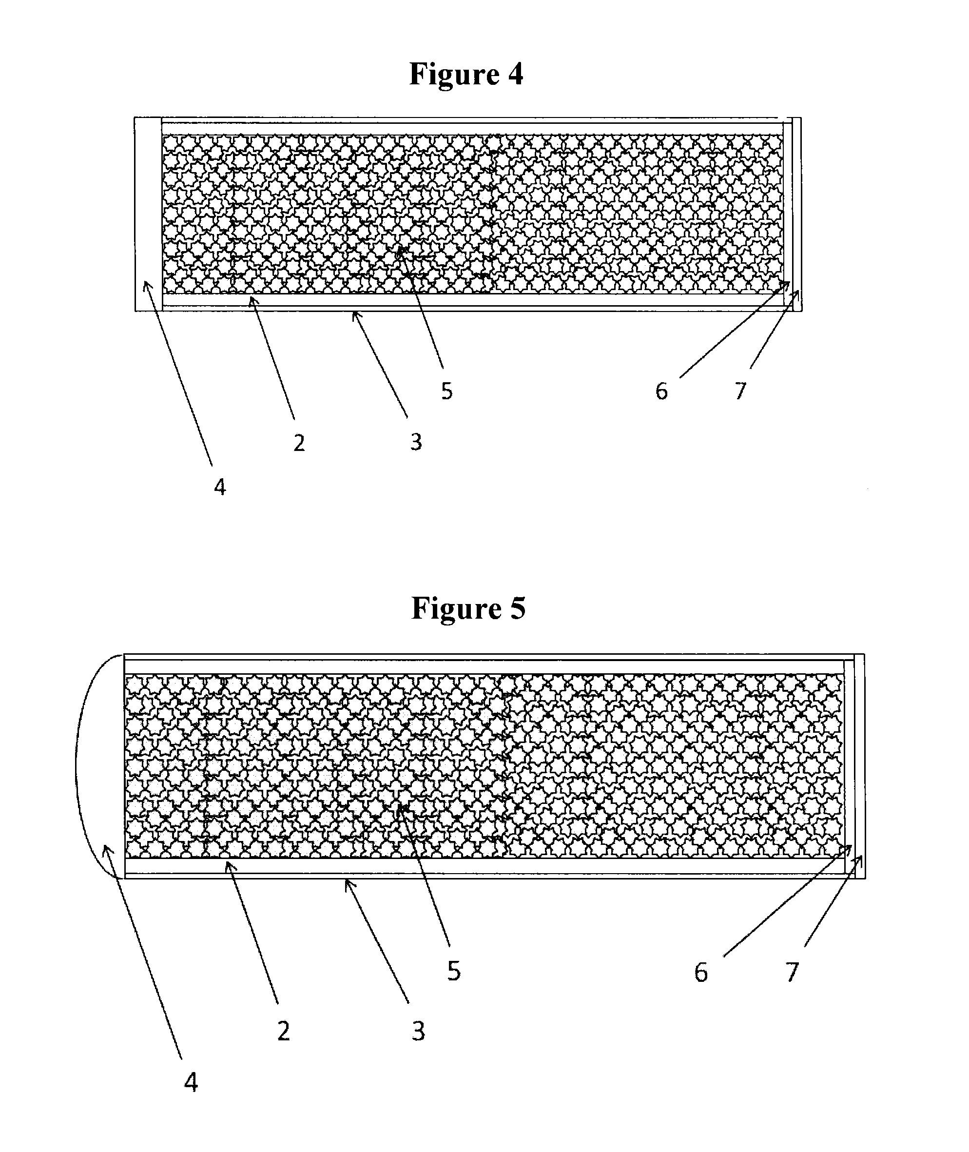
A photoluminescent capsule illuminator for a sighting device. The photoluminescent illuminator includes an elongated phosphor housing having sidewalls and a base. The photoluminescent illuminator includes phosphors in a granular form disposed inside the phosphor housing. The photoluminescent illuminator includes a cap sealing the phosphors in the phosphor housing. The phosphor housing is disposed in relation to a body of the sighting device such that photoluminescent light emitted from the phosphors exits the phosphor housing and identifies a location of a sight on the sighting device.

Description

BACKGROUND OF THE INVENTION[0001]1. Field of the Invention[0002]The present invention relates to photoluminescent illuminators providing passive illumination of sights and other devices especially in dark or low light ambient conditions. The photoluminescent illuminators of the invention permit objects to be viewed for relatively long durations in low ambient light environments and to be recharged quickly.[0003]2. Discussion of Background[0004]Aiming sights are commonly used as a reference indicia on various weaponry such archery bows, guns, mortar and artillery sights, etc. Archery sights usually have a bracket secured to a sight assembly on the bow to support vertically spaced sight elements extending cantilevered to an end adjacent a vertical sight plane. Each of the different sight elements typically represent distinct target distances from which the archer can select in the aiming of his arrow toward an intended target. For guns, the traditional iron sights have a pair of align...

Claims


Application Information

Patent Timeline
IPC IPC(8): F41G1/32F21V13/14G01B11/02
CPCF41G1/32G01B11/02F21W2131/40F21Y2101/02F21V13/14F41G1/345F21Y2115/10
Inventor MARTIN, RICHARD JAMESBENDER, GREGORY LOUISBRIGNALL, JR., THOMAS WELLSRICHERT, HENRY JOHN
Owner DEFENSE HLDG
Why Eureka
Try Eureka