
Methods and systems for transmitting data through an aggregated connection

a technology of data transmission and aggregated connection, applied in the field of computer networks, can solve the problems of reducing the quality of the overall packet transmission, affecting the transmission speed of data, and unpredictable quality of packet transmission, so as to reduce the probability of host 103 retransmitting data-1, reduce the probability of host 103 retransmitting data, and slow down the data transmission

Active Publication Date: 2015-04-23
PISMO LABS TECH
View PDF5 Cites 13 Cited by
  • Summary
  • Abstract
  • Description
  • Claims
  • Application Information

AI Technical Summary

Benefits of technology

The present invention is about methods and systems for transmitting data packets from one device to another through multiple tunnels. When an error occurs, the first device sends a message to the second device indicating that it has not received the data packet successfully. The first device then retransmits the data packet and sends an error correction packet to the second device. The second device acknowledges the data packet and the error correction packet. The error correction mode is activated when an error is detected and deactivated when the data packet is successfully received. The data packet and the error correction packet are transmitted through different tunnels. The waiting time period for acknowledgement is set to prevent unnecessary retransmits. The technical effect of the invention is to improve data transmission reliability and efficiency.

Problems solved by technology

It is notable, however, that while a session based site-to-site VPN is able to utilize different tunnels for different sessions, a single download session in this type of connection is only able to utilize one tunnel.
In wireless communications, quality of packet transmission may be unpredictable, and packet drop rate may change frequently.
This may reduce the quality of the overall packet transmission.
Even if the bandwidth limit of each tunnel is high, the packet drop rate may not improve.

Method used


Image

  • Methods and systems for transmitting data through an aggregated connection
  • Methods and systems for transmitting data through an aggregated connection
  • Methods and systems for transmitting data through an aggregated connection

Examples


Embodiment Construction

[0012]The ensuing description provides preferred exemplary embodiment(s) only, and is not intended to limit the scope, applicability or configuration of the invention. Rather, the ensuing description of the preferred exemplary embodiment(s) will provide those skilled in the art with an enabling description for implementing a preferred exemplary embodiment of the invention. It being understood that various changes may be made in the function and arrangement of elements without departing from the spirit and scope of the invention as set forth in the appended claims.

[0013]Specific details are given in the following description to provide a thorough understanding of the embodiments. However, it will be understood by one of ordinary skill in the art that the embodiments may be practiced without these specific details. For example, circuits may be shown in block diagrams in order not to obscure the embodiments in unnecessary detail. In other instances, well-known circuits, processes, algo...


PUM


Abstract

The present invention discloses methods and systems for transmitting data packets from a first communications router to a second communications router through an aggregated connection comprising a plurality of tunnels. The first communications router receives a first data packet belonging to a data session from a first host. The first communications router then transmits the first data packet to the second communications router and stores the first data packet in a local storage medium. The first communications router determines whether an error correction mode is activated. If an error correction mode is activated, the first communications router retransmits the first data packet and also transmits an error correction packet corresponding to the first data packet.

Description

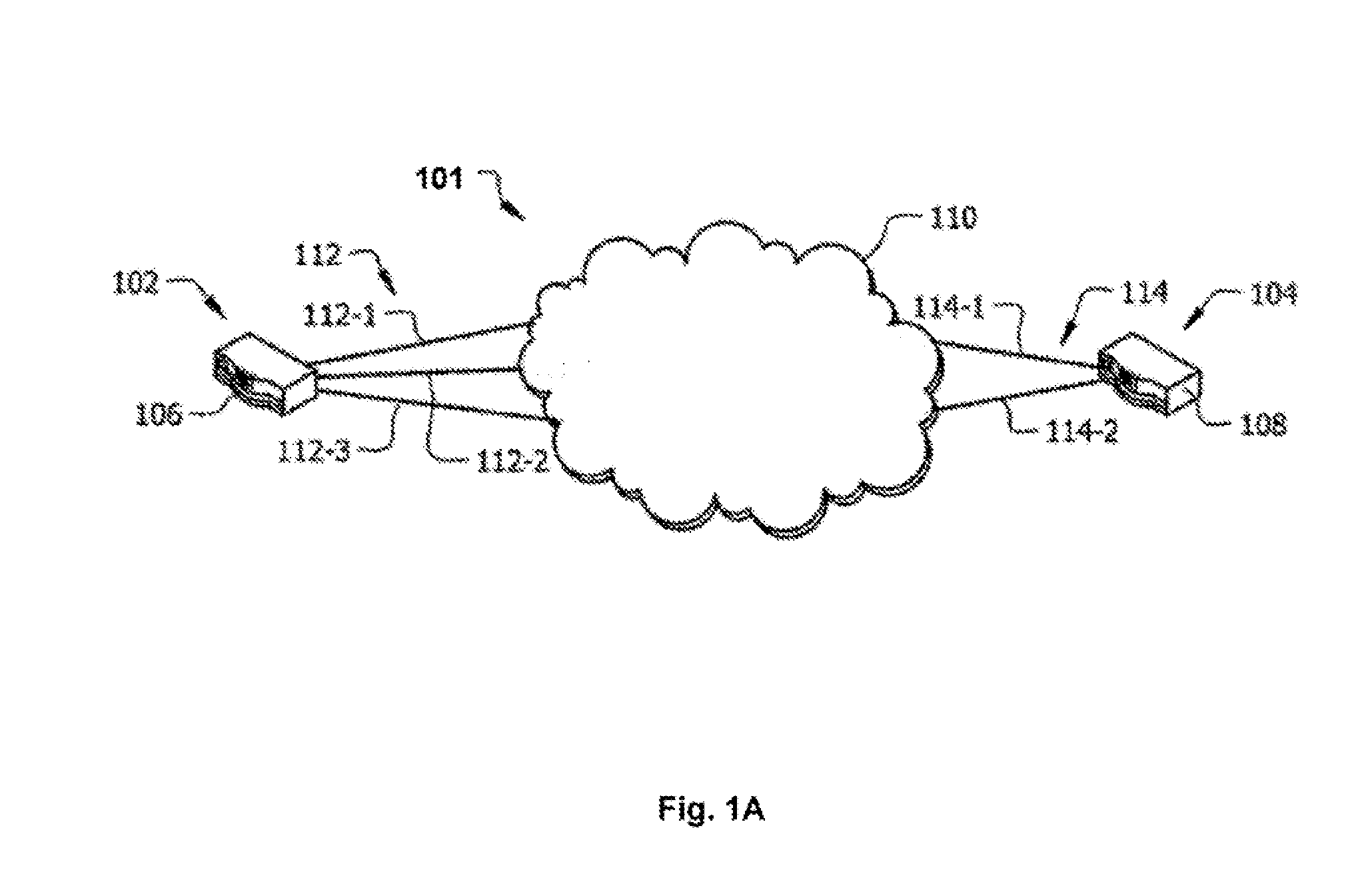
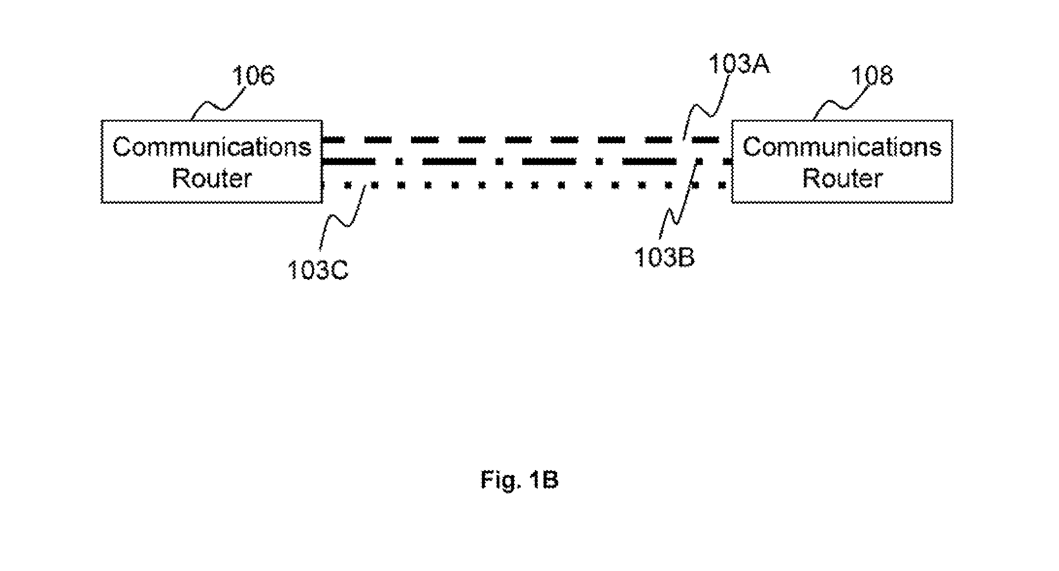
TECHNICAL FIELD[0001]The present invention relates in general to the field of computer networks. More particularly, the present invention discloses methods and systems for transmitting data packets from a first communications router to a second communications router through an aggregated connection comprising a plurality of tunnels.BACKGROUND ART[0002]A multi Wide Area Network (WAN) Site-to-Site VPN router is a router that supports aggregating the bandwidth of multiple interconnections, e.g., WAN connections for accessing one or more remote private networks. In some implementations, each TCP / IP session is routed to only one WAN. In this configuration, a single TCP file transfer session can only utilize the bandwidth of one WAN connection on each end. For example, in a session based site-to-site virtual private network (VPN) connection VPN traffic is routed to multiple WAN connections between two sites (e.g., sites A and B).[0003]In one implementation, M×N tunnels are initially forme...

Claims


Application Information

Patent Timeline
IPC IPC(8): H04L1/08
CPCH04L1/08H04L1/203H04L1/1825H04L2001/0096
Inventor SUNG, PATRICK HO WAING, KAM CHIUCHAN, HO MING
Owner PISMO LABS TECH
Learn More