Work apparatus

a work apparatus and work technology, applied in the field of work apparatuses, can solve the problems of harsh attack on the operator, difficult to thoroughly discharge the accumulated charge, and operator should feel very uncomfortabl

Active Publication Date: 2015-04-30
MAKITA CORP
View PDF2 Cites 27 Cited by
  • Summary
  • Abstract
  • Description
  • Claims
  • Application Information

AI Technical Summary

Benefits of technology

[0008]In view of the foregoing circumstances, therefore, it is a primary object of the present invention to obviate the above-mentioned inconveniences residing in the conventional work apparatuses, and to provide a work apparatus such as a blower apparatus and a suction apparatus in which the operator would not be attacked by electrostatic discharge from the airflow tube such as a blowoff tube and a suction tube which the user holds and operates when in use.
[0010]With the work apparatus configured as above in which an electrically conductive member is arranged within the airflow tube at least in the range between the position where the holding device is provided and the open distal end of the airflow tube, and in which an electrically grounding member electrically connected to the electrically conductive member and configured to be touchable to earth is provided at the open distal end of the airflow tube, the operator can easily have the electrically grounding member touch the ground while the operator is holding the grip handle of the airflow tube to blow out or suck in air through the airflow tube, whereby the electrostatic charge generated on the airflow tube will be discharged to the ground before attacking the operator's hands from the grip handle.
[0013]Further, in the work apparatus configured as above, the electrically conductive wire may be further extended beyond the open distal end of the airflow tube and may droop from the open distal end to constitute the electrically grounding member, so that the drooping part would easily touch the ground, even though the operator should not carefully control the open distal end of the airflow tube to touch the ground while holding the grip handle.

Problems solved by technology

Under these circumstances, when the user or operator of the blower apparatus holds the grip handle provided on the airflow tube, the electrostatic charge accumulated on the airflow tube would burst through to the hand of the operator, giving a harsh attack to the operator.
The operator should feel very uncomfortable.
With the second example as mentioned above in which the electrostatic charge on the potential compensating conductor and the engine is expected to be conducted away to the ground through the operator, it would be hard to thoroughly discharge the accumulated charge.
Both of the above mentioned inconveniences would be obviated by hanging a conductive chain from the engine to reach the ground, but such an arrangement would cause another inconvenience for the operator to erroneously step on the chain during the operation.

Method used


Image

  • Work apparatus
  • Work apparatus
  • Work apparatus

Examples


Embodiment Construction

[0026]The invention and its various embodiments can now be better understood by turning to the following detailed description of the preferred embodiments with reference to the accompanying drawings. The embodiments of the work apparatuses hereunder described are a backpack blower apparatus and a backpack suction apparatus.

[0027]It should be expressly understood that the illustrated embodiments are presented just as practicable examples of the invention and that the invention as defined by the claims may be broader than the illustrated embodiments described below. In the drawing, like reference characters refer to like parts so that repetitive explanations may be omitted.

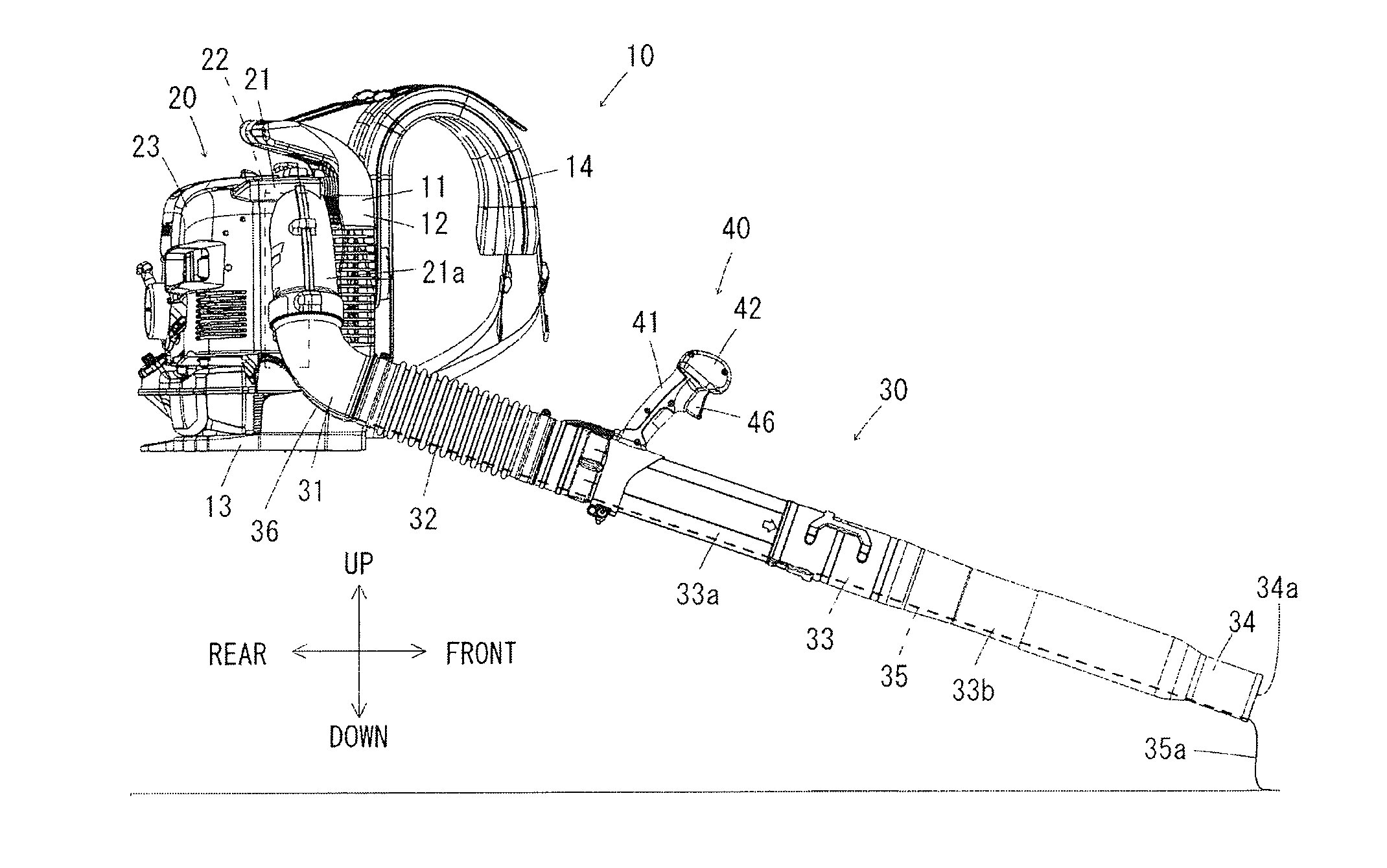
[0028]FIG. 1 illustrates a backpack blower apparatus 10, which comprises a back carrier frame 11 for being piggybacked by the user, a blower unit 20 including a blow-out duct (airflow duct) 21a and mounted on the back carrier frame 11, and an airflow tube (blowoff tube) 30 coupled to the blow-out duct 21a for blowin...


PUM


Abstract

A work apparatus is comprised of a blower unit including a drive motor; a volute casing, a fan rotatably supported within the volute casing and driven by the drive motor, and an airflow duct connected to the volute casing, thereby blowing out or sucking in air through the airflow duct; and of an airflow tube coupled to the airflow duct of the blower unit and having an open distal end for blowing out or sucking in air through the airflow tube. The airflow tube is provided with a grip handle adapted for being held and operated by the operator. Within the airflow tube is arranged an electrically conductive wire at least between the grip handle and the open distal end, beyond which is provided an electrically grounding wire connected to the electrically conductive wire and drooping therefrom to be touchable to earth.

Description

[0001]TECHNICAL FIELD[0002]The present invention relates to a work apparatus such as a blower apparatus and a suction apparatus comprising a power-operated blower unit and an airflow tube adapted to be used for blowing off fallen leaves or sucking in dust on the ground or the like. More particularly, the present invention relates to a work apparatus so contrived that electrostatic charge which would otherwise accumulate on the airflow tube during operation of the work apparatus could be effectively conducted away to earth.BACKGROUND INFORMATION[0003]Blower apparatuses have been conventionally known and used in the art as a kind of work apparatuses used for blowing off fallen leaves on the ground or the like. A blower apparatus comprises a power-operated blower unit and an airflow tube (blowoff tube). The blower unit includes a drive motor, a volute casing, a fan rotatably supported within the volute casing and driven by the drive motor, and an airflow duct (a blow-out duct) connecte...

Claims


Application Information

Patent Timeline
Patent Type & Authority Applications(United States)
IPC IPC(8): A47L5/14A47L9/28
CPCA47L9/2889A47L5/14A47L9/248E01H1/08E01H1/0809H05F3/025
Inventor FUKUNAGA, KONASHIMOTO, TOMONOBUSHIBATA, YOSHINORI
Owner MAKITA CORP
Why Eureka
Try Eureka