Gas Turbine Combustor and Gas Turbine Combustor Control Method

Inactive Publication Date: 2015-04-30
MITSUBISHI HITACHIPOWER SYST LTD
View PDF0 Cites 8 Cited by
  • Summary
  • Abstract
  • Description
  • Claims
  • Application Information

AI Technical Summary

Benefits of technology

[0007]The present invention makes it possible to implement a gas turbine combustor and a gas turbine combustor control

Problems solved by technology

However, it is anticipated that a local fuel-air ratio may increase due to the drift of air in the combustor to cause a local rise in the metal temperature of the combustor liner and an increase in the amount of NOx.
In such an instance, the flow rate of combustion air supplied to a burner disposed at a circumferential position at which the flow rate of

Method used


Image

  • Gas Turbine Combustor and Gas Turbine Combustor Control Method
  • Gas Turbine Combustor and Gas Turbine Combustor Control Method
  • Gas Turbine Combustor and Gas Turbine Combustor Control Method

Examples


Example

First Embodiment

[0019]The gas turbine combustor and the gas turbine combustor control method according to a first embodiment of the present invention will now be described with reference to FIGS. 1 to 6.

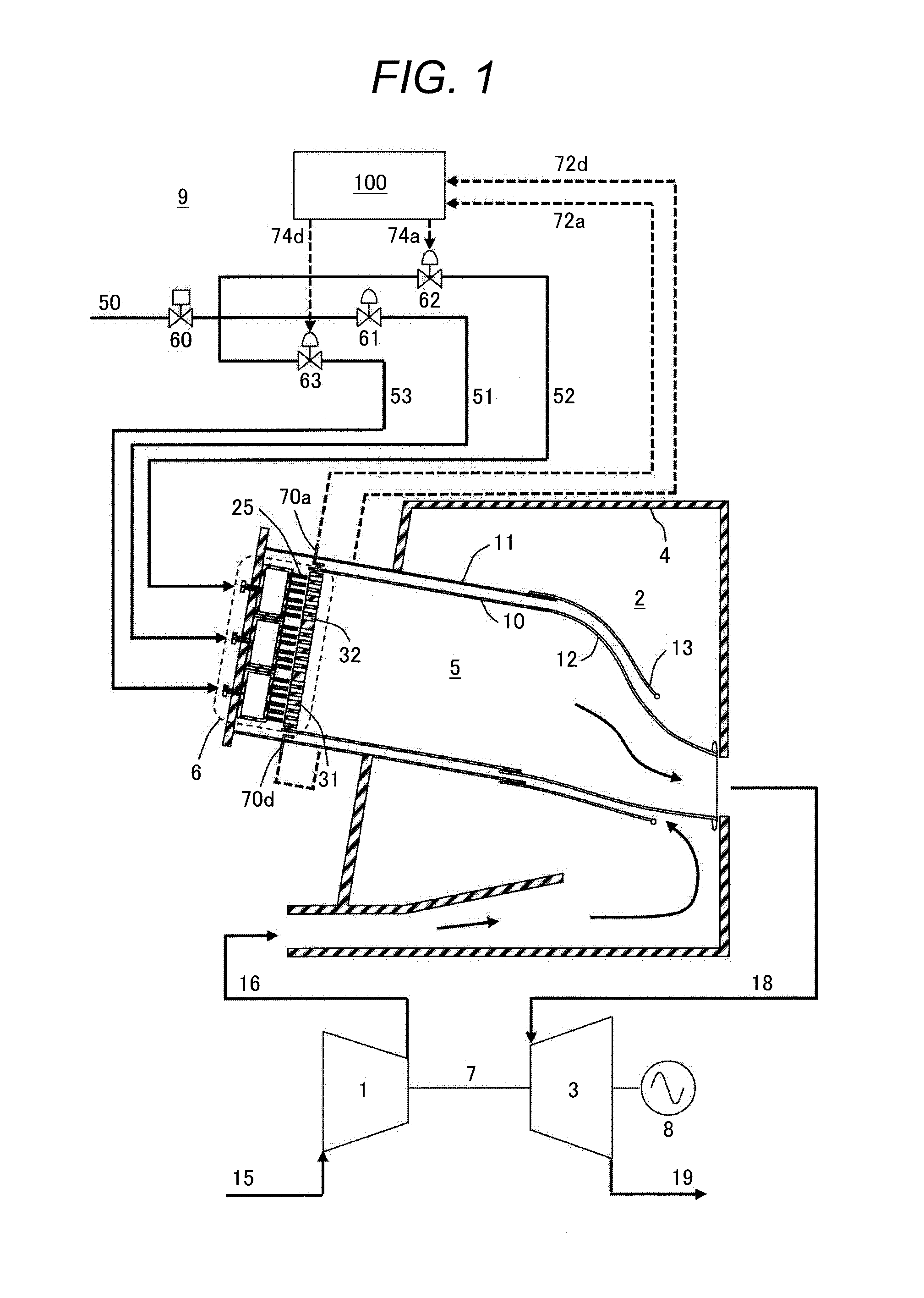
[0020]FIG. 1 is a system diagram illustrating an overall configuration of a power generation gas turbine plant.

[0021]In the gas turbine plant 9 shown in FIG. 1, a power generation gas turbine includes a compressor 1, a gas turbine combustor 2, a turbine 3, a generator 8, and a shaft 7. The compressor 1 generates high-pressure air 16 by compressing intake air 15. The gas turbine combustor 2 mixes the high-pressure air 16 generated by the compressor 1 with a gas fuel 50 and burns the resulting mixture to generate a high-temperature combustion gas 18. The turbine 3 is driven by the high-temperature combustion gas 18 generated by the gas turbine combustor 2. The generator 8 rotates to generate electrical power when the turbine 3 is driven. The shaft 7 couples the compressor 1, the turbin...

Example

Second Embodiment

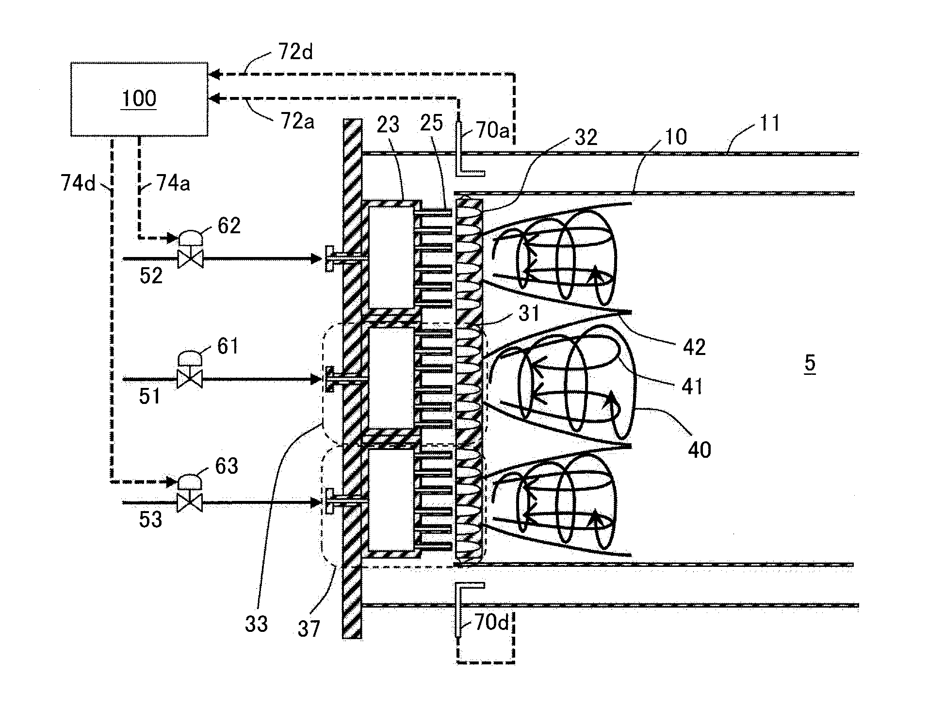
[0072]FIG. 7 is a cross-sectional view, as viewed from the combustion chamber, illustrating the air hole plate portion of the gas turbine combustor according to a second embodiment of the present invention. In the second embodiment, the number of pitot tubes 70, which act as the flow velocity measurement units, is decreased. A total of four pitot tubes 70a, 70d, 70g, 70h are disposed. The pitot tube 70a is disposed on an upper portion of the multi-burner 6. The pitot tube 70d is disposed on a lower portion of the multi-burner 6. The pitot tubes 70g, 70h are disposed on the other portions.

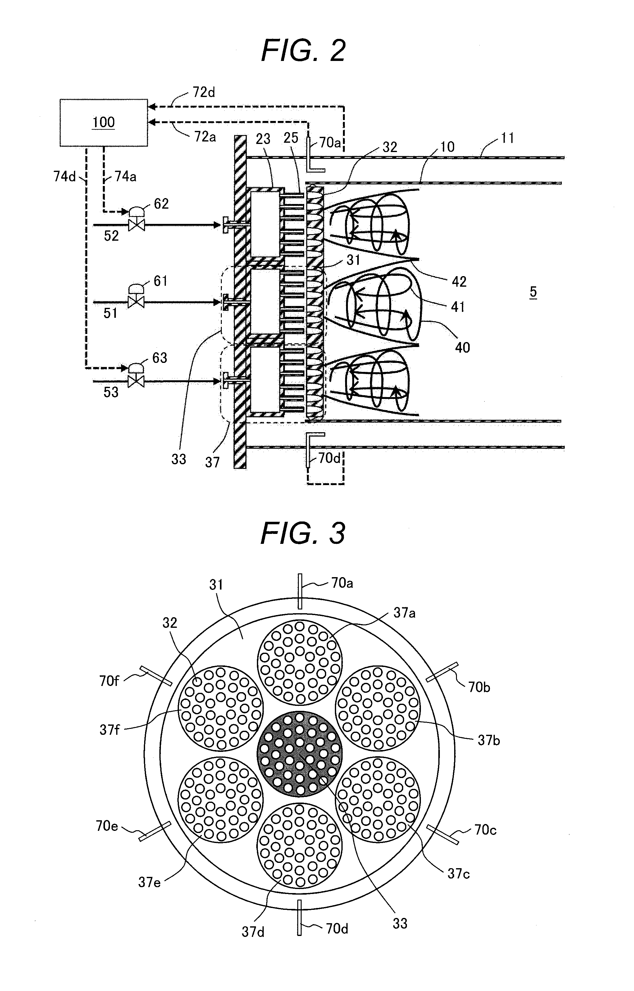
[0073]As the outer burner 37b and the outer burner 37c are vertically symmetrical to each other, the pitot tube 70g may representatively measure the flow velocities of two sectors. In such an instance, flow velocity information measured by the pitot tube 70g is used to calculate the fuel-air ratio of an outer burner positioned toward the pitot tube 70h. When the flow velocity inform...

Example

Third Embodiment

[0076]FIG. 9 illustrates a configuration of the gas turbine combustor in a casing in accordance with a third embodiment of the present invention. In the third embodiment, which relates to the gas turbine combustor of a multi-can combustor type, the disposition of multi-burners 6 (combustor cans) in the casing, which distributes air from the outlet of the compressor to each combustor can, is described.

[0077]In all the disposed multi-burners 6a-6h, the present embodiment adjusts the fuel flow rate in accordance with the flow velocity distribution in the circular flow path formed between the flow sleeve 11 and the combustor liner 10. Each multi-burner 6 includes a total of two pitot tubes 70. One pitot tube is disposed toward the inner circumference, and the other pitot tube is disposed toward the outer circumference.

[0078]FIG. 10 illustrates a modification of the third embodiment. In this modified embodiment, the number of multi-burners 6 for measuring the flow velocit...


PUM


Abstract

The burners include a central burner and a plurality of outer burners disposed around the central burner. Each of the outer burners is equipped with a fuel supply system that includes a fuel flow regulating valve. The outer circumference of the combustor liner is provided with a cylindrical flow sleeve. At least one flow velocity measurement unit is disposed in a circular flow path formed between the combustor liner and the flow sleeve to measure the flow velocity of air flowing downward. The gas turbine combustor also includes a control device that adjusts the fuel flow rate of the fuel, which is to be supplied to the outer burners, in accordance with the flow velocity of the air in the circular flow path, which is measured by the flow velocity measurement units.

Description

CLAIM OF PRIORITY[0001]The present application claims priority from Japanese Patent application serial no. 2013-221722, filed on Oct. 25, 2013, the content of which is hereby incorporated by reference into this application.FIELD OF THE INVENTION[0002]The present invention relates to a gas turbine combustor and to a gas turbine combustor control method.BACKGROUND OF THE INVENTION[0003]From the viewpoint of environmental load reduction, it is demanded that NOx emissions from a gas turbine be further reduced. As a measure of reducing the NOx emissions from a gas turbine combustor, a premixed burner is employed to reduce the amount of cooling air for a combustor liner, thereby enleaning an air-fuel premixture. However, it is anticipated that a local fuel-air ratio may increase due to the drift of air in the combustor to cause a local rise in the metal temperature of the combustor liner and an increase in the amount of NOx. A technology disclosed in Japanese Unexamined Patent Application...

Claims


Application Information

Patent Timeline
IPC IPC(8): F02C9/34F23N1/00F23R3/16F23R3/46F23R3/00
CPCF02C9/34F23R3/46F23R3/002F23R3/16F23N1/00F23R2900/03043F05D2270/44F23N2037/02F05D2270/082F05D2270/112F05D2270/301F23N2035/12F23N2025/06F23N2041/20F23N5/18F23R3/286F23N2241/20F23N2225/06F23N2235/12F23N2237/02
Inventor TATSUMI, TETSUMANUMATA, SHOHEIYOKOTA, OSAMI
Owner MITSUBISHI HITACHIPOWER SYST LTD
Why Eureka
Try Eureka