Gas turbine combustion control device and combustion control method and program therefor

a technology of combustion control device and combustion control method, which is applied in the direction of combustion air/fuel air treatment, machines/engines, mechanical equipment, etc., can solve the problems of affecting the reliability affecting the affecting the output and efficiency of the compressor, so as to achieve stable operation of the gas turbine, suppress the generation of combustion oscillation, and increase the effect of nox

Active Publication Date: 2017-03-30
MITSUBISHI POWER LTD
View PDF12 Cites 4 Cited by
  • Summary
  • Abstract
  • Description
  • Claims
  • Application Information

AI Technical Summary

Benefits of technology

[0030]According to the above-described gas turbine combustion control device and combustion control method and program therefor, even when normal operation is switched to anti-icing operation, stable combustion control of the combustors is maintained, so that an increase in NOx, etc. can be avoided and generation of combustion oscillation can be suppressed. As a result, stable operation of the gas turbine is realized. Moreover, it is possible to realize stable operation while meeting emission regulation values even during turndown operation (partial load operation).

Problems solved by technology

When the icing phenomenon occurs, not only is the reliability of the gas turbine adversely affected due to the resulting decrease in output and efficiency of the gas turbine, but also the blades and vanes in a front stage of the compressor may be damaged as the accumulated ice falls away.

Method used


Image

  • Gas turbine combustion control device and combustion control method and program therefor
  • Gas turbine combustion control device and combustion control method and program therefor
  • Gas turbine combustion control device and combustion control method and program therefor

Examples


embodiment 1

[0052]Gas turbine combustion control device and combustion control method of Embodiment 1 according to the present invention will be described with reference to FIG. 1 to FIG. 9.

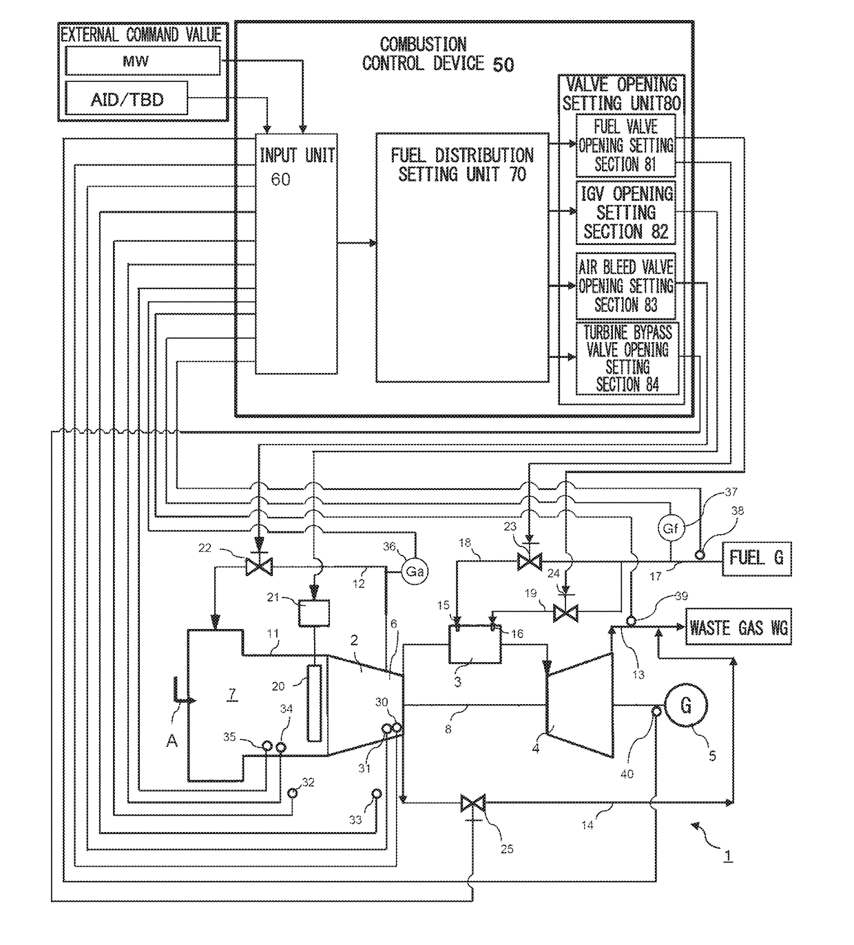
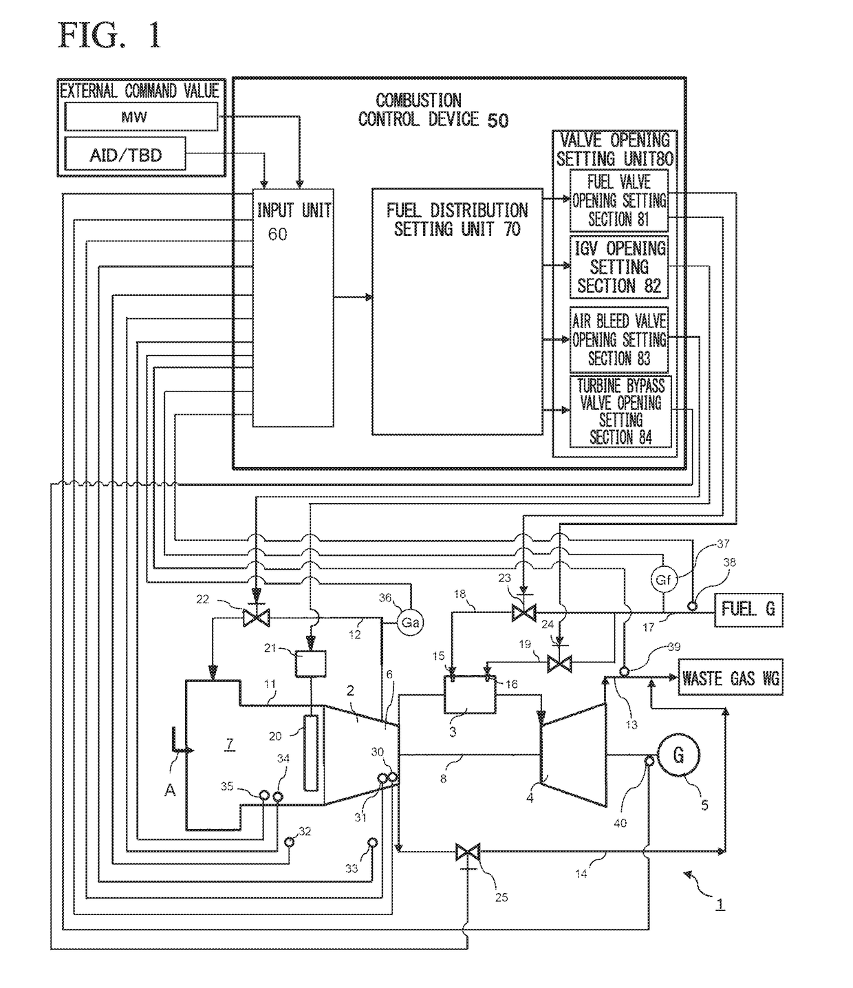
[0053]FIG. 1 shows the device configuration of a gas turbine of Embodiment 1. A gas turbine 1 is composed mainly of a compressor 2, combustors 3, a turbine 4, and a combustion control device 50, and electric power is taken out by a generator 5 connected to a rotating shaft 8.

[0054]The compressor 2 pressurizes and compresses atmospheric air A taken in through an air intake facility 7, and temporarily stores the compressed air A in a casing 6 of the compressor 2. The combustor 3 mixes a fuel G and the compressed air A supplied from the casing 6 and combusts the mixture to produce high-temperature combustion gas. The turbine 4 has a configuration in which multiple stages of blades fixed to the rotating shaft 8 and multiple stages of vanes supported on the casing are alternately disposed. The turbine 4 introduce...

embodiment 2

[0104]Next, Embodiment 2 will be described with reference to FIG. 10 to FIG. 12.

[0105]This embodiment is different from Embodiment 1 in that a first database 90a related to the first operation mode and a second database 90b related to the second operation mode are prepared, and that a modified turbine inlet temperature-equivalent control variable (MCLCSO) in the predetermined operation (actual operation) mode in anti-icing operation is calculated from these databases.

[0106]In other words, the two embodiments are different in that the database 70a with reference only to the first operation mode is used in Embodiment 1 while the databases 90a, 90b with reference to both the first operation mode and the second operation mode are used in Embodiment 2.

[0107]In FIG. 10, as preparation, the first database 90a related to the first operation mode and the second database 90b related to the second operation mode are created of the relations between the control parameters and the turbine output...

embodiment 3

[0130]Next, Embodiment 3 will be described with reference to FIG. 13.

[0131]In both Embodiment 1 and Embodiment 2, the relations between the turbine output (generator output MW) or the turbine inlet temperature and the control parameters are made into a database on the basis of the input data (input data group) 61 transmitted from the input unit 60, and the fuel distribution ratios for the fuel circuits and the valve openings are set on the basis of the database. Embodiment 3 is different from Embodiment 1 and Embodiment 2 in that the relations between the turbine inlet temperature (TIT) and the input data 61 are made into a database without using any control parameter, and the valve openings of the valves are set on the basis of the database.

[0132]While the configuration of the database in this embodiment is different from that of the other embodiments, the basic concept of the modification method, in which a database related to the first operation mode and a database related to the...


PUM


Abstract

A combustion control device is installed in a gas turbine including a compressor, a combustor, a turbine, a turbine bypass pipe through which compressed air from a casing is discharged to a turbine downstream part so as to bypass the turbine, and a turbine bypass valve that regulates a turbine bypass flow rate of the compressed air. The combustion control device includes: a fuel distribution setting unit that sets a turbine inlet temperature or a turbine inlet temperature-equivalent control variable on the basis of input data, and sets fuel distribution ratios on the basis of the turbine inlet temperature or the turbine inlet temperature-equivalent control variable; and a fuel valve opening setting section that sets the valve openings of fuel regulating valves. The fuel distribution setting unit includes correction means for modifying the fuel distribution ratios.

Description

TECHNICAL FIELD[0001]The present invention relates to gas turbine combustion control device and combustion control method and a program therefor, and more particularly, to a combustion control device, a combustion control method, and a program that are applied to a gas turbine in anti-icing operation or turndown operation (partial load operation).BACKGROUND ART[0002]Commonly, the flow rate of combustion air supplied to a gas turbine is controlled through the opening of inlet guide vanes (IGVs) etc. The opening of the IGVs is smaller during no load operation or partial load operation of the gas turbine than during rated load operation. Especially when the atmospheric temperature falls in winter, an icing phenomenon of moisture in the air forming ice may occur at the inlet part of the compressor. When the icing phenomenon occurs, not only is the reliability of the gas turbine adversely affected due to the resulting decrease in output and efficiency of the gas turbine, but also the bla...

Claims


Application Information

Patent Timeline
Patent Type & Authority Applications(United States)
IPC IPC(8): F02C9/52F02C9/18F02C9/28F02C7/04
CPCF02C9/52F02C7/04F05D2270/303F02C9/28F02C9/18F02C9/54F05D2270/08F05D2270/31F05D2270/71F02C9/26
Inventor UYAMA, NORIYOSHIHARUTA, HIDEKIAKIZUKI, WATARUKOMAGOME, YUJITAKAOKA, KOJIIWASAKI, YOSHIFUMI
Owner MITSUBISHI POWER LTD
Why Eureka
Try Eureka