
Annular premixed pilot in fuel nozzle

a fuel nozzle and pilot technology, applied in the ignition of turbine/propulsion engine, combustion type, lighting and heating apparatus, etc., can solve the problems of unstable operation of gas turbine engine and gas turbine engine performance, and achieve the effect of increasing nox

Inactive Publication Date: 2015-09-10
GENERAL ELECTRIC CO
View PDF12 Cites 8 Cited by
  • Summary
  • Abstract
  • Description
  • Claims
  • Application Information

AI Technical Summary

Benefits of technology

The patent describes a new fuel nozzle design for gas turbine engines that helps achieve a more uniform relationship between the fuel and air that combusts at a given temperature. This design reduces the generation of nitrogen oxides as a byproduct of combustion. Additionally, the patent suggests using a premix pilot to stabilize the pilot flame and prevent an increase in NOx even at low fuel to air ratios. Overall, this design improves the efficiency and reduces emissions of gas turbine engines.

Problems solved by technology

However, there is a trade-off in performance of the gas turbine engine.
For as the ratio of fuel to air that is combusted is lowered, there is an increased tendency of the flame of the fuel nozzle to blow out and thus render unstable the operation of the gas turbine engine.

Method used


Image

  • Annular premixed pilot in fuel nozzle
  • Annular premixed pilot in fuel nozzle
  • Annular premixed pilot in fuel nozzle

Examples


Embodiment Construction

[0025]Reference will now be made in detail to present embodiments of the invention, one or more examples of which are illustrated in the accompanying drawings. The detailed description uses numerical and letter designations to refer to features in the drawings. Like or similar designations in the drawings and description have been used to refer to like or similar parts of embodiments of the invention.

[0026]Each example is provided by way of explanation of the invention, not limitation of the invention. In fact, it will be apparent to those skilled in the art that modifications and variations can be made in the present invention without departing from the scope or spirit thereof. For instance, features illustrated or described as part of one embodiment may be used on another embodiment to yield a still further embodiment. Thus, it is intended that the present invention covers such modifications and variations as come within the scope of the appended claims and their equivalents.

[0027...


PUM


Abstract

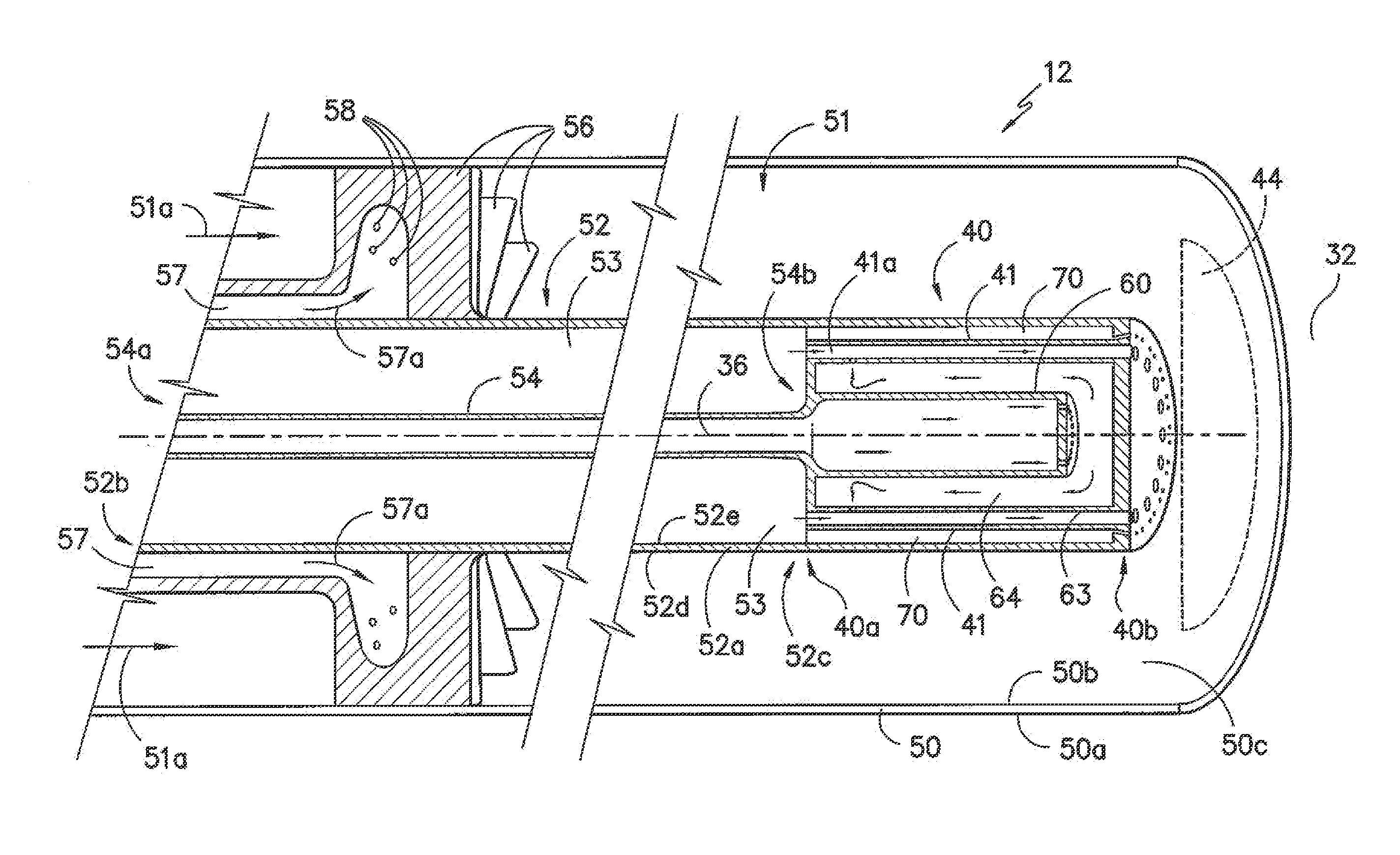
A combustor for a gas turbine engine has a head end portion that carries at least one fuel / air nozzle. Each fuel / air nozzle includes a premixed pilot nozzle having premix conduits where each premix conduit has an upstream end defining an opening and having a central axis and downstream end defining an outlet and having a central axis where the central axis of the downstream end is non-parallel with a central axis of a center body of the fuel / air nozzle. The premixed pilot nozzle can include an annular channel disposed radially outwardly from the premix conduits and may include air jets that direct air radially outwardly from the premix conduits.

Description

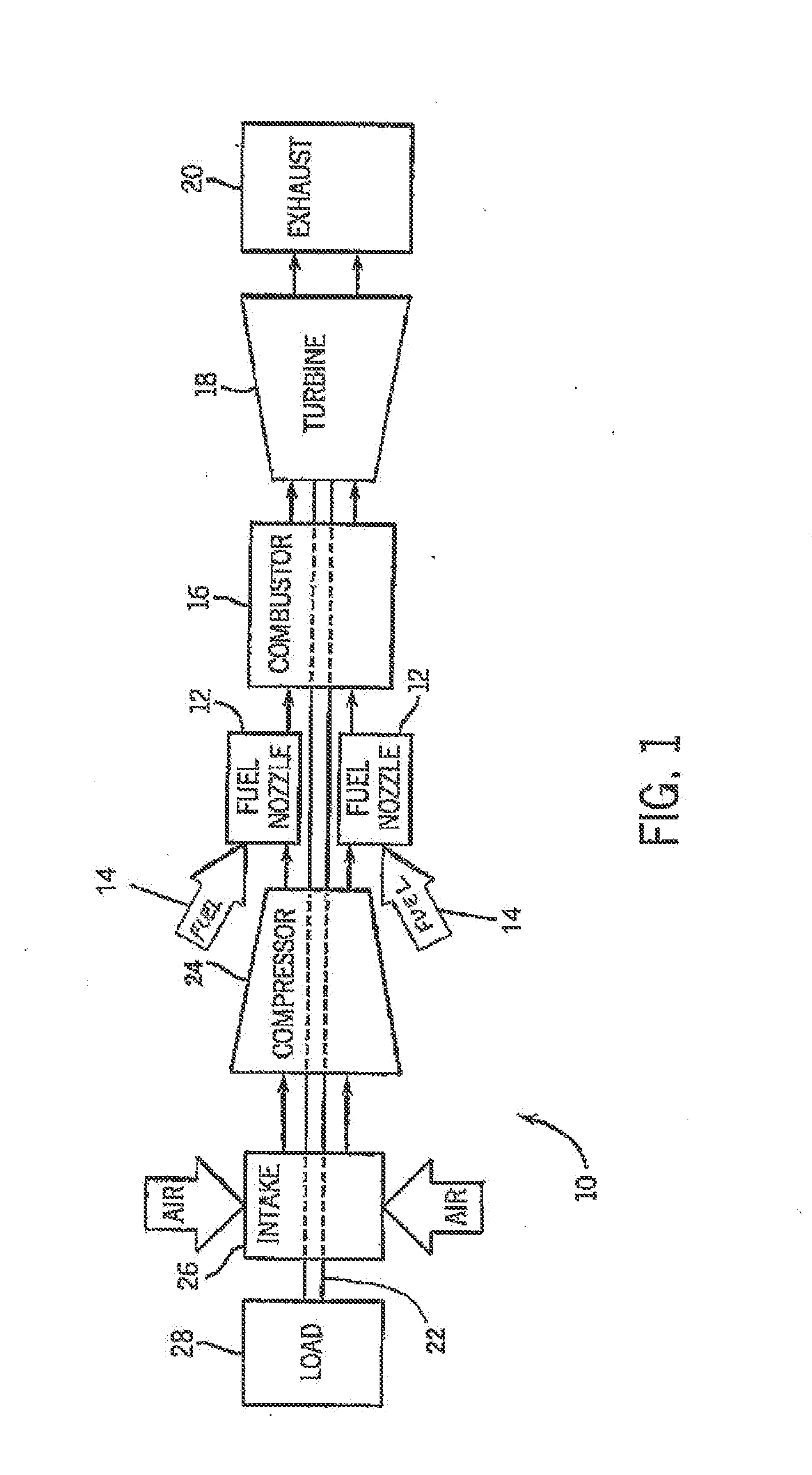
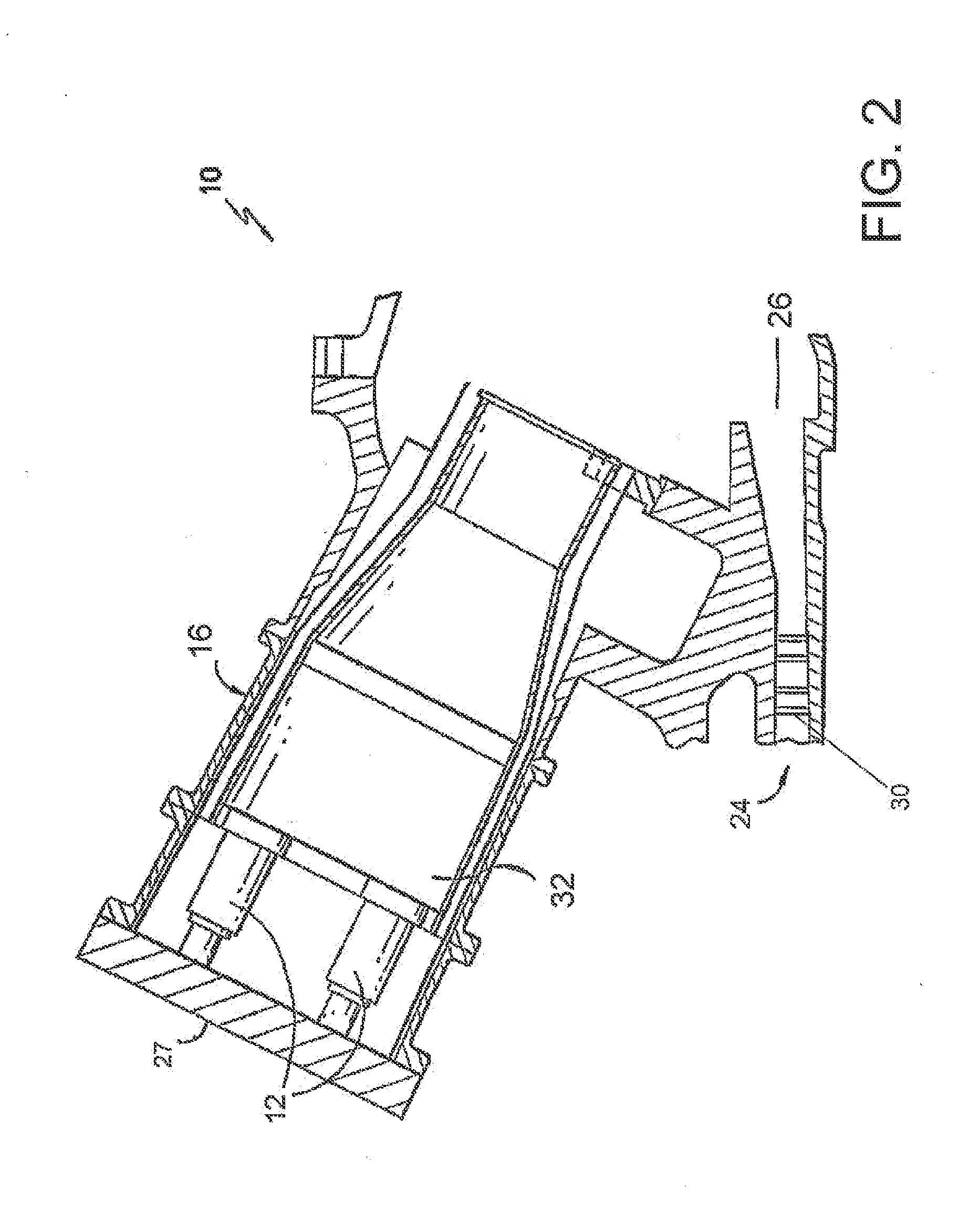
CROSS-REFERENCE TO RELATED APPLICATIONS[0001]The present application is a continuation application of U.S. application having Ser. No. 13 / 405,550 filed on Feb. 27, 2012, which is incorporated herein in its entirety by reference thereto for all purposes. Any disclaimer that may have occurred during prosecution of the above-referenced application(s) is hereby expressly rescinded.FIELD OF THE INVENTION[0002]The present invention generally involves a gas turbine engine that combusts a hydrocarbon fuel mixed with air to generate a high temperature gas stream that drives turbine blades to rotate a shaft attached to the blades and more particularly to the engine's fuel nozzle having a pilot nozzle that premixes fuel and air while achieving lower nitrogen oxides.BACKGROUND OF THE INVENTION[0003]Gas turbine engines are widely used to generate power for numerous applications. A conventional gas turbine engine includes a compressor, a combustor, and a turbine. In a typical gas turbine engine, ...

Claims


Application Information

Patent Timeline
Patent Type & Authority Applications(United States)
IPC IPC(8): F23R3/28F23R3/34
CPCF23R3/343F23R3/286F23R3/14F23C7/004F23D14/08F23C2900/07001F23R2900/03343
Inventor UHM, JONG HOSIMONS, DERRICK WALTERBOARDMAN, GREGORY ALLENROMIG, BRYAN WESLEYEDWARDS, KARAHUGHES, MICHAEL JOHN
Owner GENERAL ELECTRIC CO
Learn More