Gas Turbine Combustor

a combustor and gas turbine technology, applied in the direction of machines/engines, combustion types, lighting and heating apparatuses, etc., can solve the problems of increasing the number of parts, reducing the stability of combustion, and increasing the number of fuel systems, so as to reduce the amount of air differences, simplify the fuel supply system, and reduce the effect of air differen

Active Publication Date: 2015-05-21
MITSUBISHI POWER LTD
View PDF6 Cites 9 Cited by
  • Summary
  • Abstract
  • Description
  • Claims
  • Application Information

AI Technical Summary

Benefits of technology

[0009]This suppresses any differences in the amount of air at the fuel injecting ports of the inner circumferential and outer circumferential fuel nozzles due to pressure variations in the combustor or flow passage resistance of the fuel nozzles themselves. A desired amount of air can therefore be supplied to the fuel injecting ports of the fuel nozzles. The above vane arrangement is also effective for rectifying a flow of air in an axial direction of the burner section, and thus enables combustion stability to be enhanced. In addition, since the combustion state can be stabilized even without dividing a fuel supply system, a simplified fuel supply system can be formed by integrating fuel supply systems into one.
[0010]In the present invention, the desired amount of combustion air can be guided to the fuel injecting ports of the fuel nozzles and a desired fuel-air ratio can be stably obtained for each of the circumferential fuel nozzle arrays. This enhances the stability of the combustion state and enables NOx emissions to be reduced. Additionally a simplified fuel supply system can be formed by integrating fuel supply systems into one.

Problems solved by technology

In addition, a problem of reduced combustion stability will arise from instability of a flow rate of the air in certain positions.
The resulting increase in the number of fuel systems poses further problems such as an increased number of parts, increased manufacturing costs, and complicated maintenance.

Method used


Image

  • Gas Turbine Combustor
  • Gas Turbine Combustor
  • Gas Turbine Combustor

Examples


first embodiment

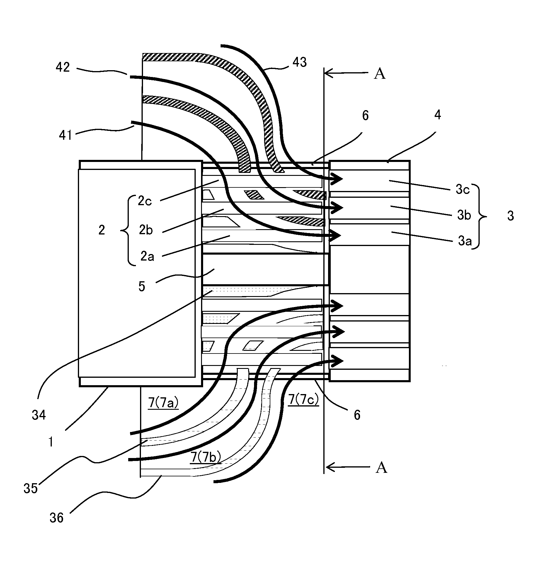
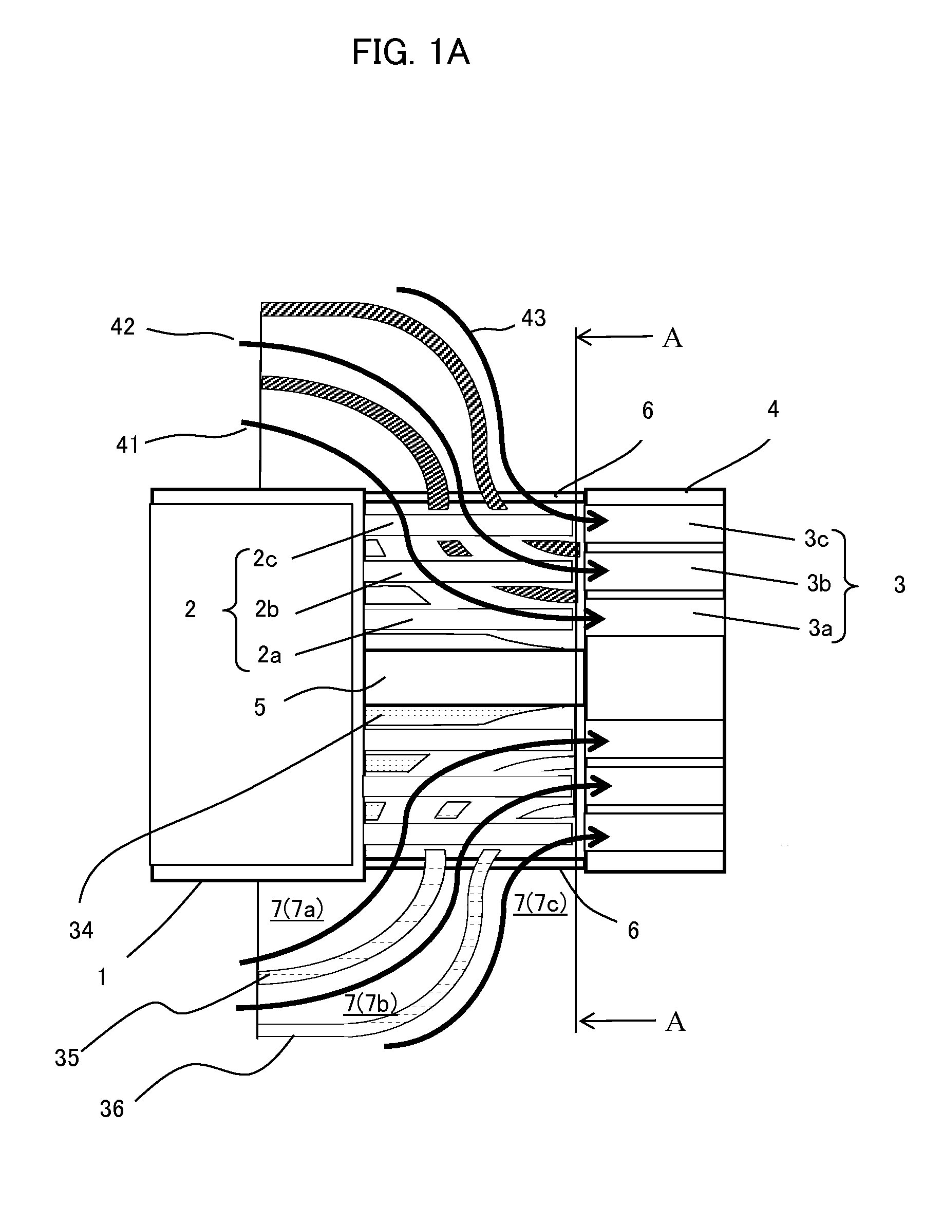
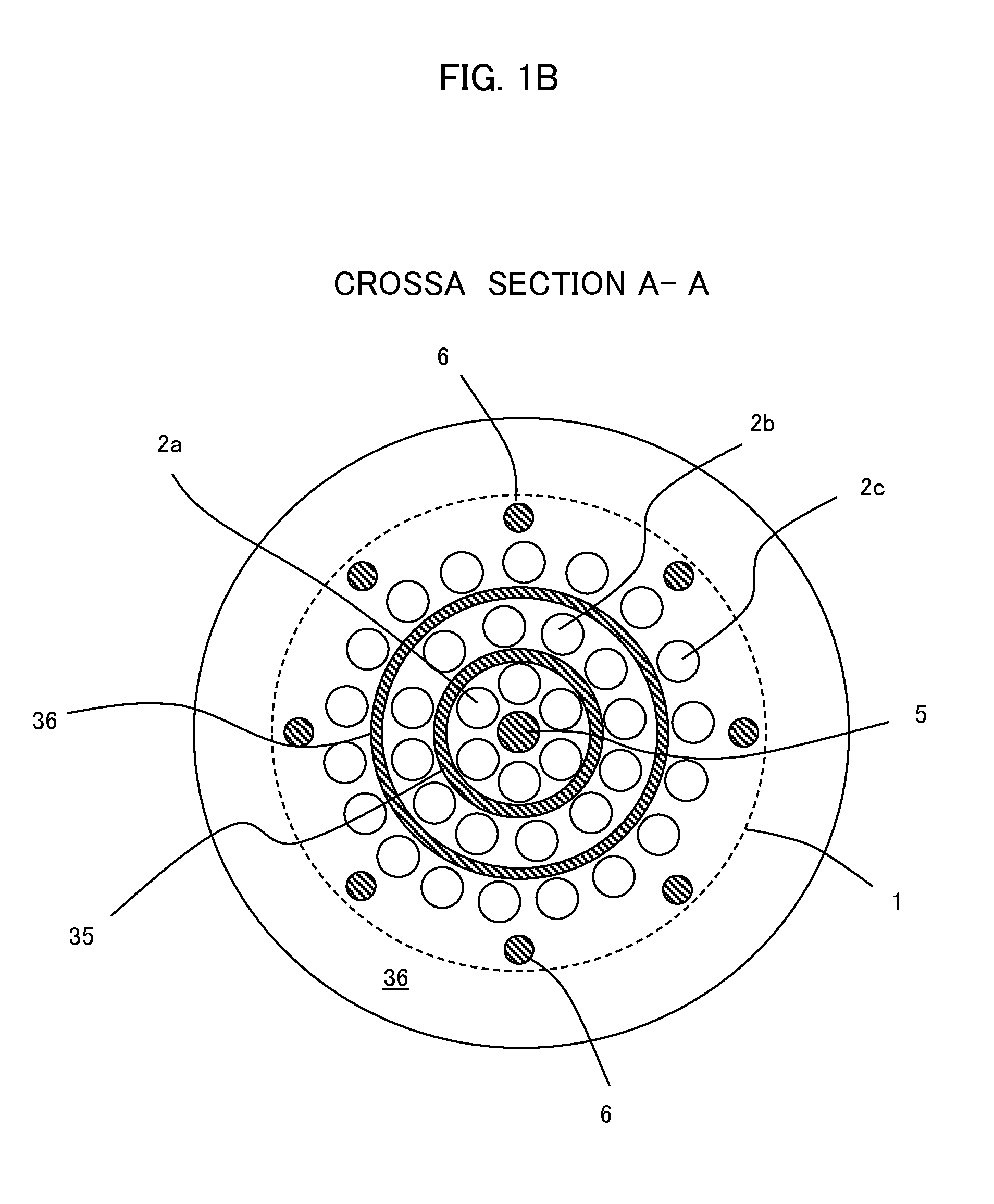
[0021]FIGS. 1A and 1B show construction of a burner section of a gas turbine combustor according to the present invention, FIG. 1A being a sectional view and FIG. 1B being an external view of cross section A-A in FIG. 1A, taken from a direction of arrows.

[0022]Referring to FIGS. 1A and 1B, the burner section of the gas turbine combustor is a cluster-type burner that includes a plurality of fuel nozzles 2 and a premixing plate 4 in which are formed a plurality of premixing passages 3 each positioned at a downstream side of one of the fuel nozzles 2. The plurality of fuel nozzles 2 are connected to an end face of a fuel nozzle header 1, and the premixing plate 4 is connected to the end face of a fuel nozzle header 1 via a central support rod 5 and a plurality of outer circumferential support rods 6. The plurality of fuel nozzles 2 include three arrays of fuel nozzles, namely an inner circumferential fuel nozzle 2a, a central fuel nozzle 2b, and an outer circumferential fuel nozzle 2c,...

fourth embodiment

[0043]the present invention is described below using FIGS. 6A and 6B. FIG. 6A is an external view equivalent to an upper half of the central support rod 5 and central guide vane 35 of the burner section in FIG. 1B. FIG. 6B is an external view of cross section B-B in FIG. 6A, taken from a direction of arrows.

[0044]The present embodiment is characterized by the fact that in addition to the guide vane 35, a protruding vane 63 for rectifying an axial flow of combustion air is disposed on an inner circumferential surface of the guide vane 35, near a downstream end of this guide vane. The protruding vane 63, as shown, is a triangular vane whose vertex as viewed in transverse section faces toward a central axis of the vane. Mounting the triangular vane 63 in plurality and spacing the plurality of triangular vanes 63 in a circumferential direction and in parallel with respect to the axial direction allows the axial flow of the combustion air to be rectified and guided to the fuel injecting ...


PUM


Abstract

A gas turbine combustor including a cluster-type burner is adapted to stabilize a combustion state by supplying a desired flow rate of combustion air to inner circumferential and outer circumferential fuel nozzle regions. A burner section of the combustor includes a plurality of fuel nozzles 2 and a premixing plate 4 in which are formed a plurality of premixing passages 3 each positioned at a downstream side of the corresponding one of the fuel nozzles 2, injected fuel from the plurality of fuel nozzles 2 being mixed with air in the premixing passage 3 before being supplied to a combustion chamber and burnt therein. The burner section also includes guide vanes 34, 35, 36 that rectify a flow of air and guide this air flow from an upstream side of the fuel nozzles 2 to fuel injecting ports of the fuel nozzles 2; wherein the guide vanes guide a desired amount of air to the fuel injecting ports of the fuel nozzles and stabilize combustion.

Description

BACKGROUND OF THE INVENTION[0001]1. Field of the Invention[0002]The present invention relates generally to gas turbine combustor. More particularly, the invention is directed to gas turbine combustor including a cluster-type burner that injects a fuel from a plurality of fuel nozzles into a plurality of premixing passages formed in a premixing plate, then after mixing in the premixing passages the injected fuel and a flow of air guided to fuel injecting ports of the fuel nozzles, supplies the mixed fuel and air to a combustion chamber, and burns the mixed fuel and air therein.[0003]2. Description of the Related Art[0004]In gas turbine combustor, emissions of nitrogen oxides (NOx), which are air pollutants, can be suppressed to a low level by using a premixed combustion scheme that forms a flame in a combustion chamber after the fuel and air have been premixed. Among known burners of the premixed combustion scheme are those of a coaxial jet flow combustion scheme in which a fuel and ...

Claims


Application Information

Patent Timeline
Patent Type & Authority Applications(United States)
IPC IPC(8): F23R3/28F23R3/46F23R3/02
CPCF23R3/286F23R3/46F23R3/02F23R3/10F23R3/14F23R3/26F23D11/40F23D14/70F23R3/04F23R3/28F23R3/283
Inventor WADA, YASUHIROSASAO, TOSHIFUMISAITO, TAKEO
Owner MITSUBISHI POWER LTD
Why Eureka
Try Eureka