Ultrasonic flowmeter

a flowmeter and ultrasonic technology, applied in the direction of instruments, measurement devices, volume/mass flow by dynamic fluid flow effect, etc., can solve the problem of influencing the ultrasonic signal

Active Publication Date: 2015-04-30
KRONE GMBH
View PDF6 Cites 9 Cited by
  • Summary
  • Abstract
  • Description
  • Claims
  • Application Information

AI Technical Summary

Benefits of technology

[0022]Based on the described prior art and the described problems resulting from the vortices generated by the transducer pocket, the object of the invention i

Problems solved by technology

If these vibrations become too strong, it is possible that the shielding interferes with the

Method used


Image

  • Ultrasonic flowmeter
  • Ultrasonic flowmeter
  • Ultrasonic flowmeter

Examples


Embodiment Construction

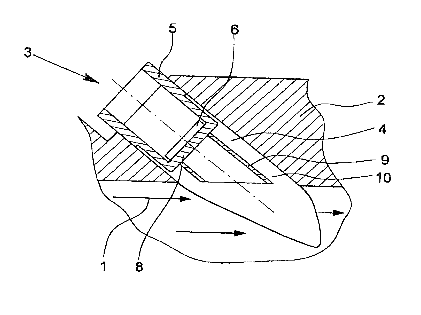
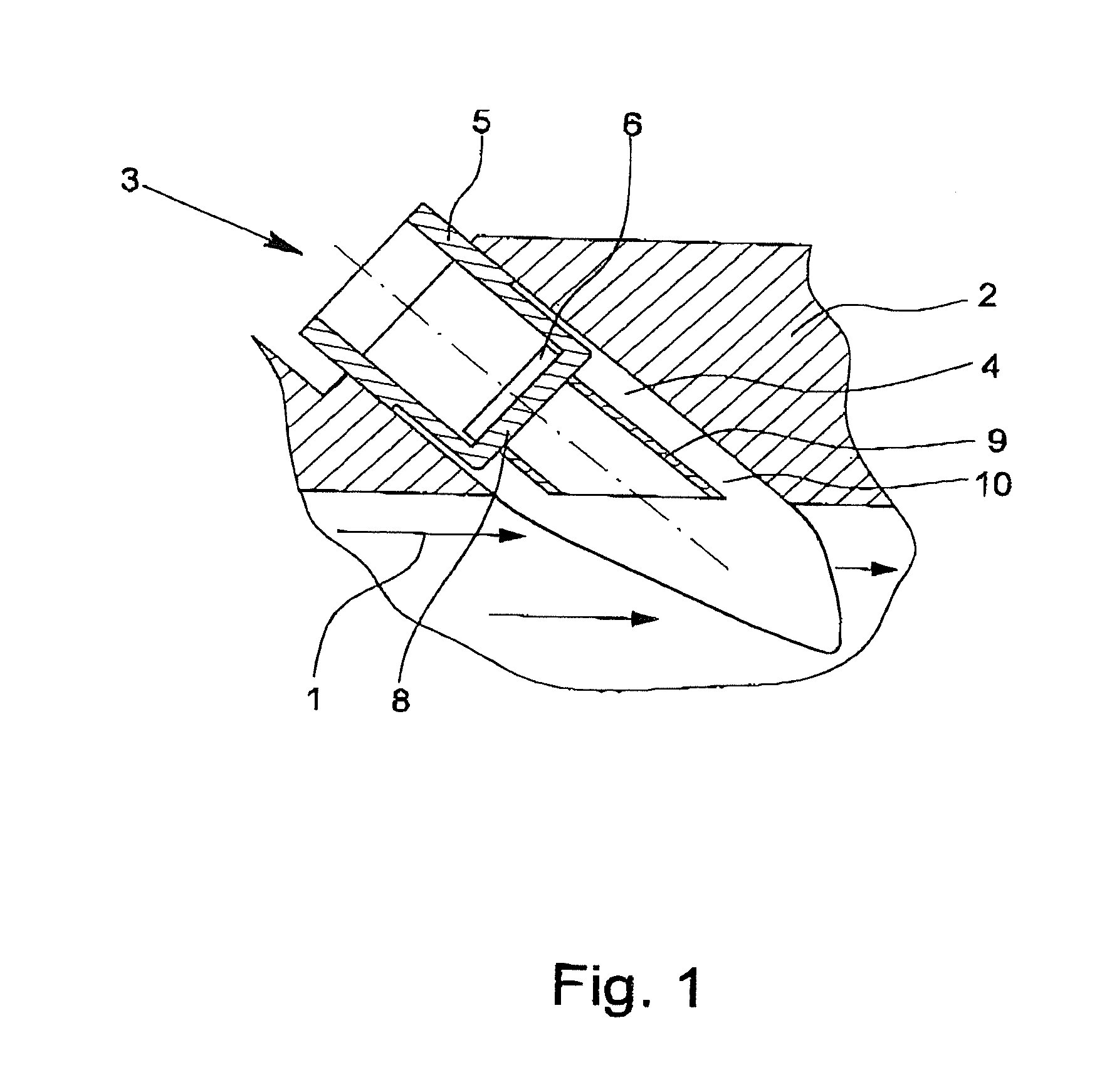
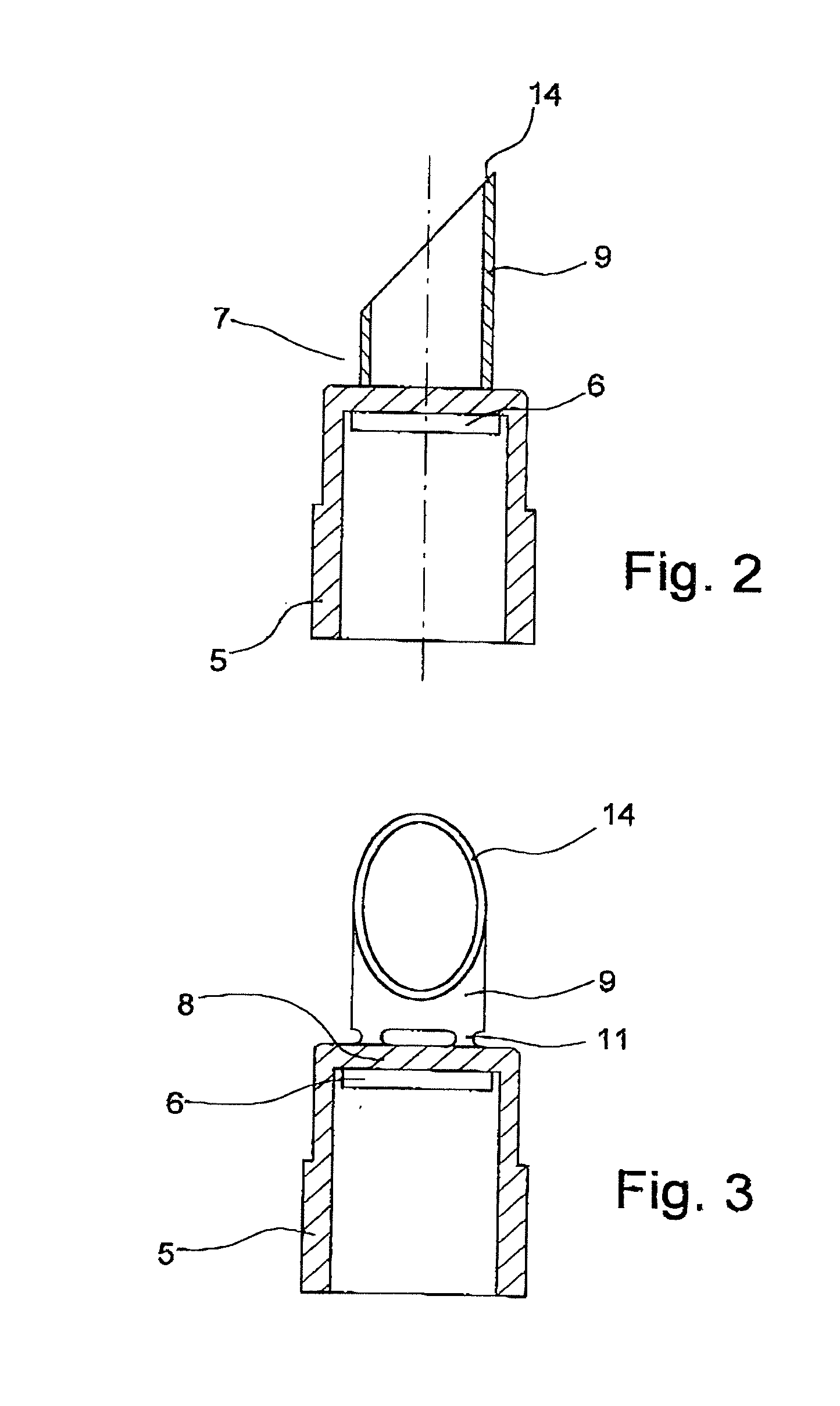
[0031]A measuring tube 2 and an ultrasonic transducer 3 of the ultrasonic flowmeter shown in FIG. 1 for measuring the flow of a flowing medium 1. The measuring tube 2 has a transducer pocket 4. The ultrasonic transducer 3 is arranged in the transducer pocket 4 of the measuring tube 2 so as to be in contact with the flowing medium 1. The ultrasonic transducer 3 has a transducer housing 5 and a transducer element 6. The transducer housing 5 has an ultrasound window 8 on a front end 7 that faces into the measuring tube 2.

[0032]According to the invention, a shielding 9 is provided, the purpose, impact and design of which being described in the following.

[0033]As seen in FIGS. 1-3, the shielding 9 is provided on the front end 7 of the transducer housing 5 facing the inside of the measuring tube 2, specifically on the ultrasound window 8 of the transducer housing 5, in the embodiments shown in these figures of the ultrasonic transducers 3 belonging to the ultrasonic flowmeters according t...


PUM


Abstract

An ultrasonic flowmeter for measuring the flow of a flowing medium (1) having a measuring tube (2) and an ultrasonic transducer (3), wherein the measuring tube (2) has a transducer pocket (4) in which the ultrasonic transducer (3) is provided in contact with the flowing medium (1) in the transducer pocket (4). The ultrasonic transducer (3) has a transducer housing (5) and a transducer element (6) and wherein the transducer housing (5) has an ultrasound window (8). The ultrasonic flowmeter solves problems resulting from vortices generated by the transducer pocket via the provision of a cylindrical shielding on the transducer housing (5).

Description

BACKGROUND OF THE INVENTION[0001]1. Field of the Invention[0002]The invention relates to an ultrasonic flowmeter for measuring the flow of a flowing medium having a measuring tube and having an ultrasonic transducer, wherein the measuring tube has a transducer pocket, wherein the ultrasonic transducer is provided having contact to the flowing medium in the transducer pocket of the measuring tube and has a transducer housing and a transducer element and wherein the transducer housing has an ultrasound window.[0003]2. Description of Related Art[0004]The ultrasonic flowmeter described above is a normal ultrasonic flowmeter insofar as it has a measuring tube and an ultrasonic transducer. In the following, however, an ultrasonic flowmeter should also be understood as one that does not have a separate measuring tube, but instead the measuring tube is an integral part of a pipe, for example, a piping system having a medium, whose flow is to be measured, flowing through it.[0005]The use of ...

Claims


Application Information

Patent Timeline
IPC IPC(8): G01F1/66G01F1/32
CPCG01F1/3209G01F1/66G01F1/662G10K11/002
Inventor VAN KLOOSTER, JEROEN MARTIN
Owner KRONE GMBH
Why Eureka
Try Eureka