Counter-flow heat exchange systems

a heat exchange system and counterflow technology, applied in the field of counterflow heat exchange systems, can solve the problems of reducing the service life of the heat exchange system, requiring costly repairs, and prone to thermomechanical fatigue (tmf)

Active Publication Date: 2015-04-30
HONEYWELL INT INC
View PDF10 Cites 73 Cited by
  • Summary
  • Abstract
  • Description
  • Claims
  • Application Information

AI Technical Summary

Problems solved by technology

Conventional plate-fin heat exchange architectures, however, are susceptible to thermo-mechanical fatigue (TMF), especially at braze connections, as they do not allo

Method used


Image

  • Counter-flow heat exchange systems
  • Counter-flow heat exchange systems
  • Counter-flow heat exchange systems

Examples


Embodiment Construction

[0020]The following detailed description is merely exemplary in nature and is not intended to limit the invention or the application and uses of the invention. As used herein, the word “exemplary” means “serving as an example, instance, or illustration.” Thus, any embodiment described herein as “exemplary” is not necessarily to be construed as preferred or advantageous over other embodiments. All of the embodiments and implementations of the heat exchange systems described herein are exemplary embodiments provided to enable persons skilled in the art to make or use the invention and not to limit the scope of the invention which is defined by the claims. Furthermore, there is no intention to be bound by any expressed or implied theory presented in the preceding technical field, background, brief summary, or the following detailed description.

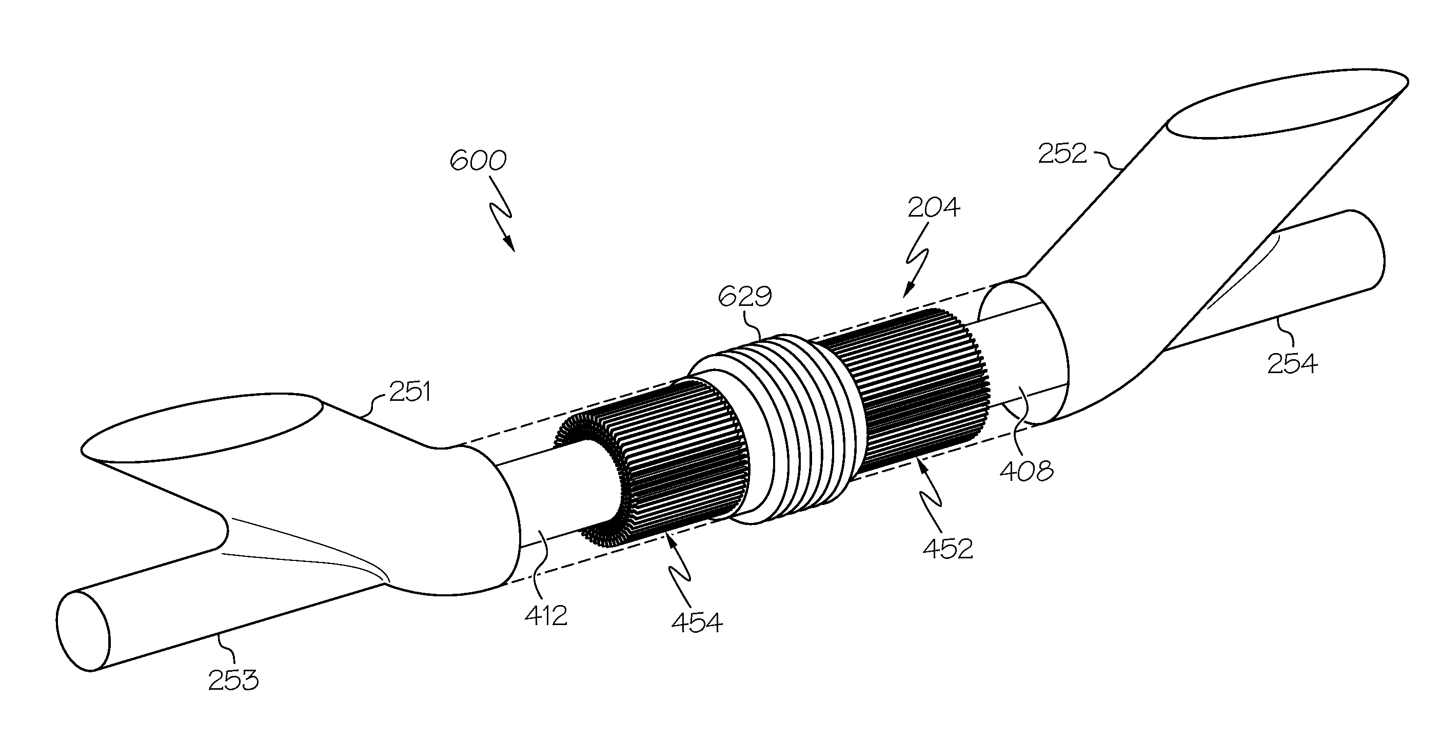
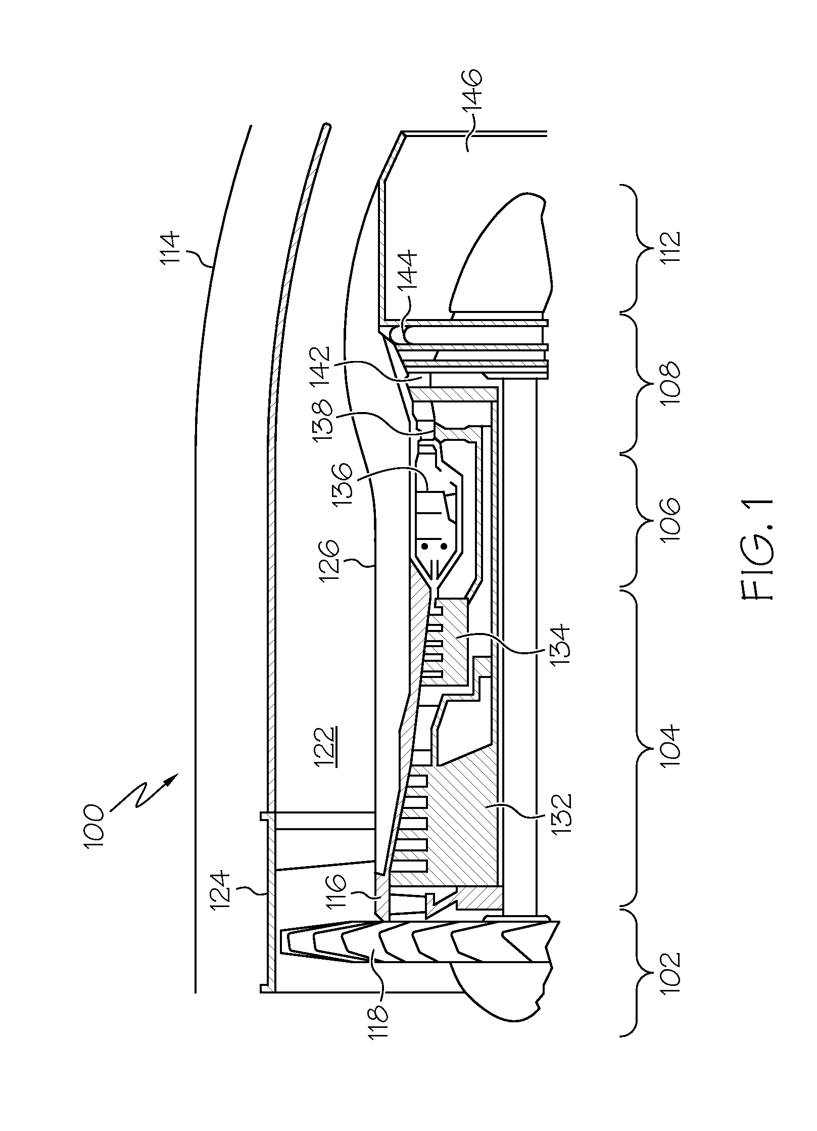
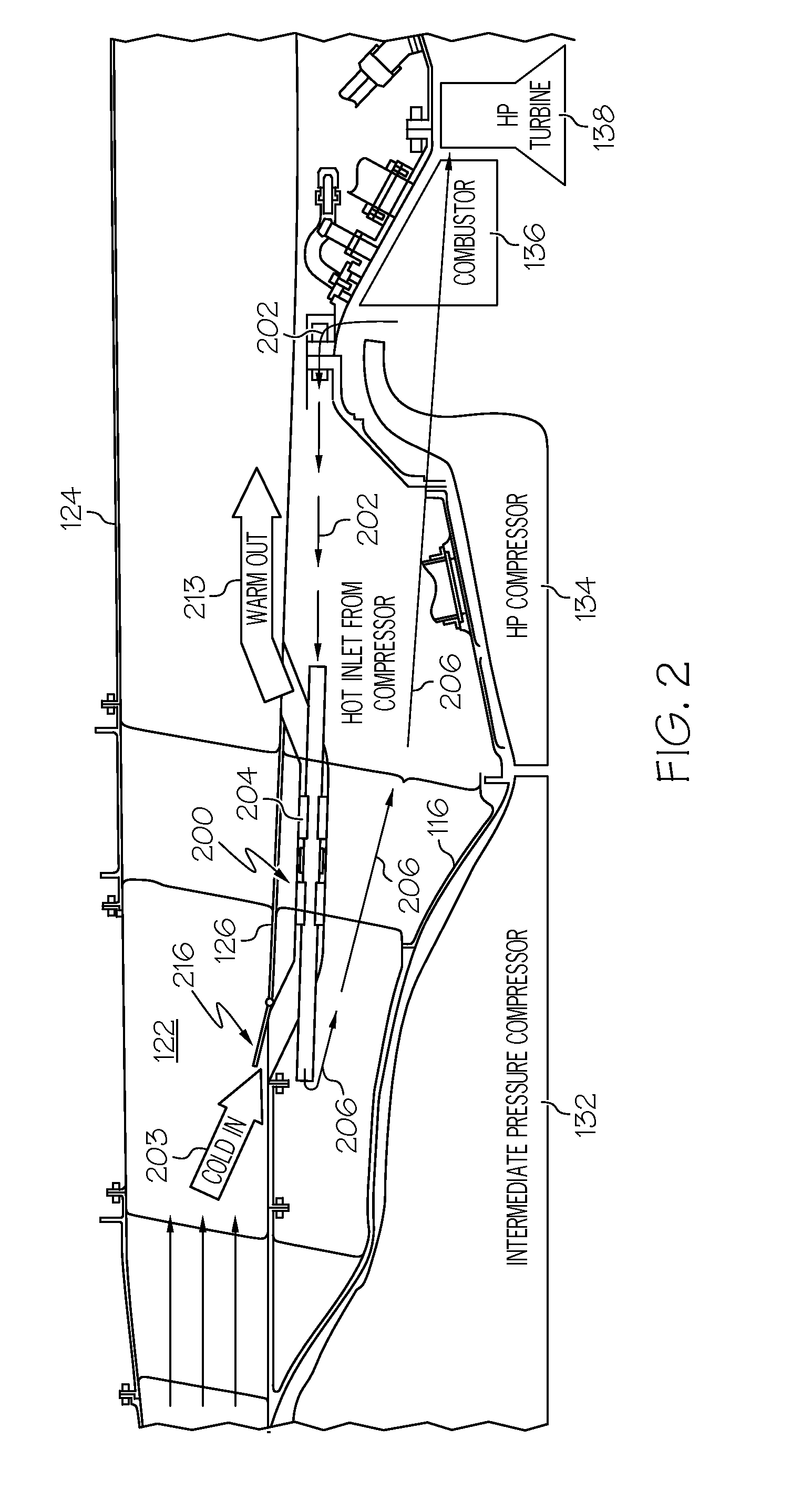
[0021]The heat exchange systems described herein are suitable for use in gas turbine engines and other applications. Particularly, the heat exch...


PUM

PropertyMeasurementUnit
Angleaaaaaaaaaa
Angleaaaaaaaaaa
Temperatureaaaaaaaaaa

Abstract

A heat exchange system includes a tubular fan air inlet portion and a tubular cooled air outlet portion connected to a first end of a tubular mid portion. The heat exchange system further includes a tubular hot air inlet portion and a tubular recycled fan air outlet portion connected a second end of the mid portion. Still further, the heat exchange system includes an integrally-formed, compliant heat exchanger tube extending between the hot air inlet portion and the cooled air outlet portion within the mid portion to define a heat exchanger first flow passage within the heat exchanger tube and a second flow passage outside of the heat exchanger tube but within the tubular mid portion. Methods for fabricating such heat exchange systems are also provided.

Description

TECHNICAL FIELD[0001]The present disclosure generally relates to heat exchange systems. More particularly, the present disclosure relates to counter-flow heat exchange systems suitable for use in gas turbine engines, among other applications.BACKGROUND[0002]In the field of gas turbine technology, a great deal of effort has been, and continues to be, directed toward improving thermodynamic efficiency by operating gas turbine engines at increasing temperatures. These temperatures may exceed the temperatures that some materials within the turbine engine structure can normally tolerate. As such, cooling air may be provided to various turbine engine components using cooling air extracted from other parts of the engine. For example, in some gas turbine engines, cooling air is extracted from a plenum at the discharge of the compressor, and is then directed to certain portions of the turbine.[0003]For some gas turbine engines, the air that is extracted from the engine for turbine cooling ma...

Claims


Application Information

Patent Timeline
IPC IPC(8): F02C7/18B23P15/26
CPCB23P15/26F02C7/185F02C7/10F28D7/106F28F1/20F28D2021/0021F28D2021/0026F28F2265/26F05D2260/213Y10T29/49361Y02T50/60F02C7/141
Inventor MORRIS, MARK C.GODFREY, DONALD G.WALDMAN, DAVID
Owner HONEYWELL INT INC
Why Eureka
Try Eureka