
Vehicle ac generator control apparatus

Active Publication Date: 2015-04-30
MITSUBISHI ELECTRIC CORP
View PDF7 Cites 4 Cited by
  • Summary
  • Abstract
  • Description
  • Claims
  • Application Information

AI Technical Summary

Benefits of technology

The present invention is a control system for the AC generator of a vehicle. It uses a magnetic-field current control system to control the value of the current flowing through the magnetic-field winding of the AC generator. This enables the torque of the AC generator to be controlled based on its rotation speed, which improves the stability of the engine.

Problems solved by technology

However, it is difficult for an ECU to instantaneously perform the calculation.
Accordingly, when the foregoing conventional vehicle AC generator control apparatus operates, it does not comprehend the rotation torque of the vehicle AC generator; therefore, it is not adequate in terms of stabilization of control of an internal combustion engine and improvement of gasoline mileage.
Moreover, in the conventional vehicle AC generator control apparatus, the output voltage of the vehicle AC generator is controlled in such a manner as described above; however, because in the regenerative braking mode, the output voltage cannot be increased up to a voltage exceeding the rated-voltage tolerance range of the vehicle battery 22, effective regenerative braking operation cannot be implemented.
Furthermore, the rotation toque of the vehicle AC generator 1 cannot accurately be comprehended; therefore, when in the idle operation mode of the internal combustion engine, the rotation torque of the vehicle AC generator 1 becomes larger than predetermined torque, the engine may stall.

Method used


Image

  • Vehicle ac generator control apparatus
  • Vehicle ac generator control apparatus
  • Vehicle ac generator control apparatus

Examples


embodiment 1

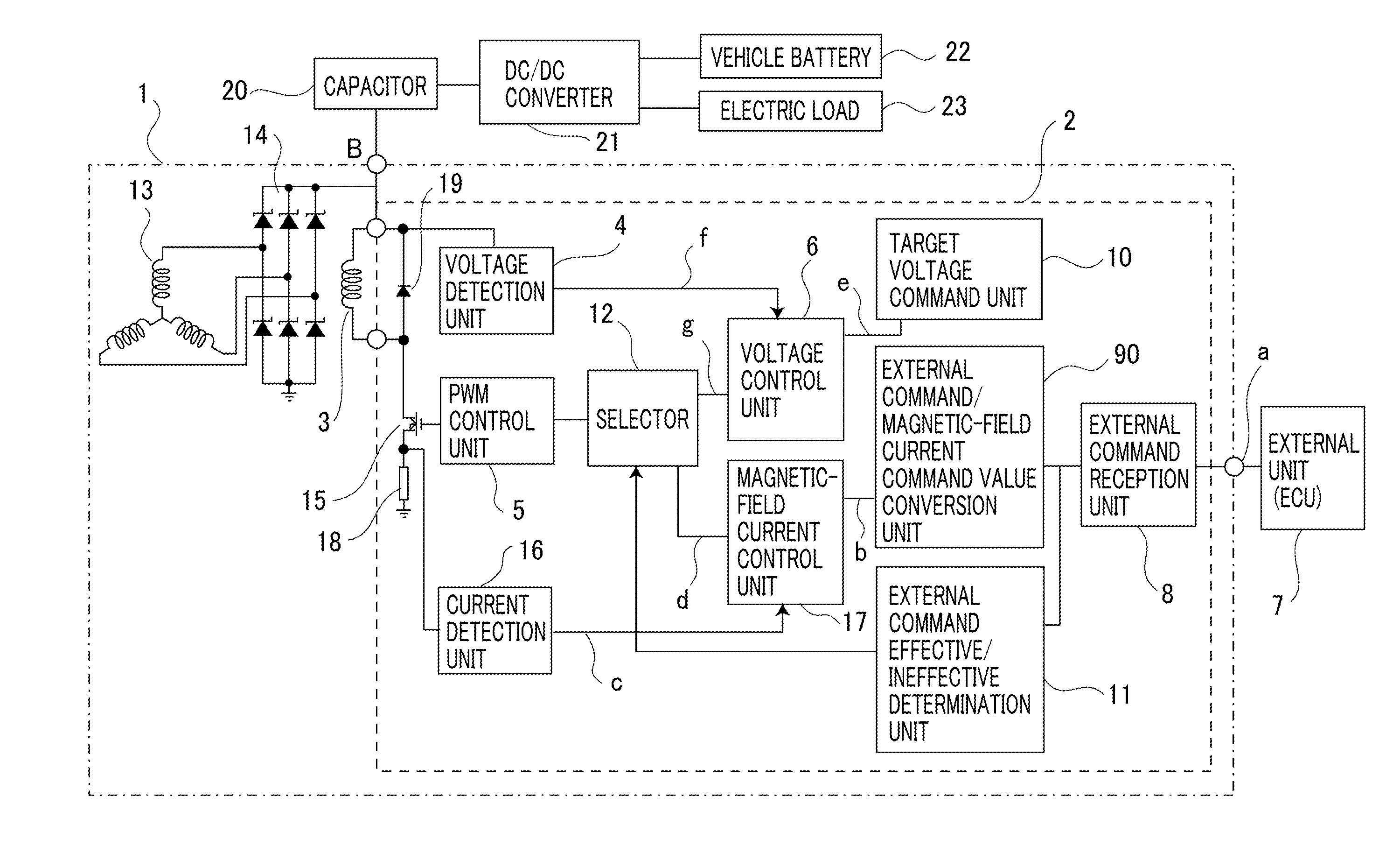
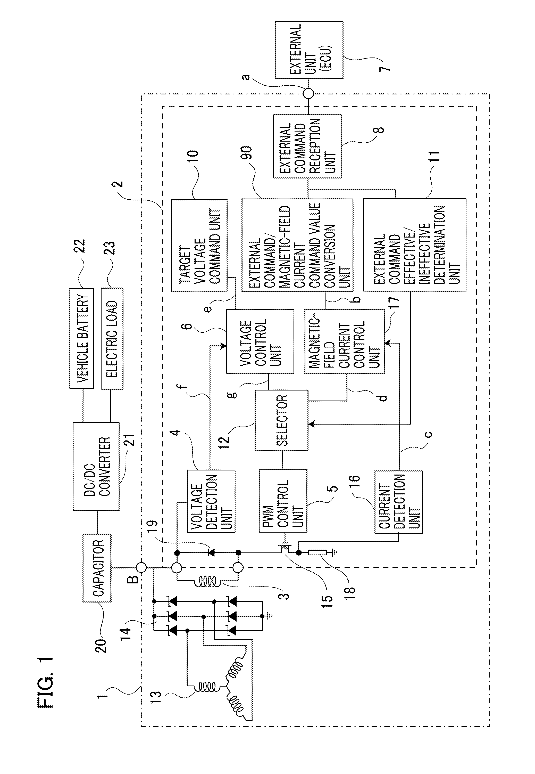
[0018]FIG. 1 is a circuit diagram representing a vehicle AC generator control apparatus according to Embodiment 1 of the present invention; only extracted part, which is related to the present invention, is illustrated. In FIG. 1, a vehicle AC generator 1 includes a stator provided with an armature winding 13 and a rotor provided with a magnetic-field winding 3. The rotor is mechanically coupled with the output axle of an internal combustion engine (unillustrated) through a torque transfer member (unillustrated) such as a belt; the vehicle AC generator 1 and the internal combustion engine transfer rotation torque to each other through the torque transfer member. The rotor of the vehicle AC generator 1 is driven to rotate by the internal combustion engine through the torque transfer member, so that three-phase AC electromotive force is induced across the armature winding 13.

[0019]A rectifier 14 converts the three-phase AC electromotive force induced across the armature winding 13 int...


PUM


Abstract

A vehicle AC generator control apparatus, the rotor of an vehicle AC generator 1 of which is coupled through a torque transfer member with the output axle of an internal combustion engine mounted in a vehicle, is provided with a magnetic-field current control system that can control the value c of a magnetic-field current flowing in a magnetic-field winding 3 of the vehicle AC generator 1 so that the magnetic-field current value c coincides with a magnetic-field current command value b; it is made possible to make the rotation torque of the vehicle AC generator 1 depend only on the rotation speed and to stabilize control of the internal combustion engine.

Description

TECHNICAL FIELD[0001]The present invention relates to a vehicle AC generator control apparatus that controls an AC power generator mounted in a vehicle such as an automobile.BACKGROUND ART[0002]As is well known, the rotor of a vehicle AC generator is coupled with the output axle of an internal combustion engine through a coupling member such as a belt; transfer of torque between the internal combustion engine and the vehicle AC generator is implemented through a coupling member. Accordingly, the operation state of the vehicle AC generator provides a considerable effect to the operation status of the internal combustion engine. To date, with regard to a control apparatus for this kind of vehicle AC generator, there has been proposed technologies in which a vehicle AC generator and an internal combustion engine are integrally controlled (for example, refer to Patent Document 1).[0003]FIG. 3 is a configuration diagram of such a conventional vehicle AC generator control apparatus as dis...

Claims


Application Information

Patent Timeline
IPC IPC(8): H02P9/00H02P9/30
CPCH02P9/008H02P2101/45H02P9/305H02P9/48
Inventor SASAKI, JUNYASUMIMOTO, KATSUYUKIKOMURASAKI, KEIICHI
Owner MITSUBISHI ELECTRIC CORP
Learn More