Phase-Switched Optical Flip-Flops Using Two-Input Bistable Resonators and Methods

a bipolar resonator and phase-switched technology, applied in the field of optical flip-flop circuits, can solve the problems of insufficient speed, robustness, and low power to be used in large numbers, and achieve the effect of fast material response, fast and robust flip-flops, and easy implementation of kerr flip-flops using microresonators

Inactive Publication Date: 2015-04-30
UNIVERSITY OF ROCHESTER
View PDF1 Cites 8 Cited by
  • Summary
  • Abstract
  • Description
  • Claims
  • Application Information

AI Technical Summary

Benefits of technology

[0004]The present invention can be embodied as a two-input bistable resonator that can be switched in a robust way by phase modulation of the input beams. An optical flip-flop of the present invention may be embodied as a two-input Kerr resonator. The disclosed switching mechanism is compatible with cross-phase modulation induced by set and reset pulses for realization of an ultrafast, passive, all-optical memory element.

Problems solved by technology

The reason for this is that flip-flops are not yet fast, robust, and low-power enough to be used in the large numbers that these applications demand.
Second, the Kerr effect has an almost instantaneous material response.
Implementation of Kerr flip-flops using microresonators has proven to be difficult.
The resulting thermo-optic change in refractive index is much stronger and slower than the Kerr effect, and as a result, switching between the “on” and “off” states is limited to microsecond time scales.

Method used


Image

  • Phase-Switched Optical Flip-Flops Using Two-Input Bistable Resonators and Methods
  • Phase-Switched Optical Flip-Flops Using Two-Input Bistable Resonators and Methods
  • Phase-Switched Optical Flip-Flops Using Two-Input Bistable Resonators and Methods

Examples


Embodiment Construction

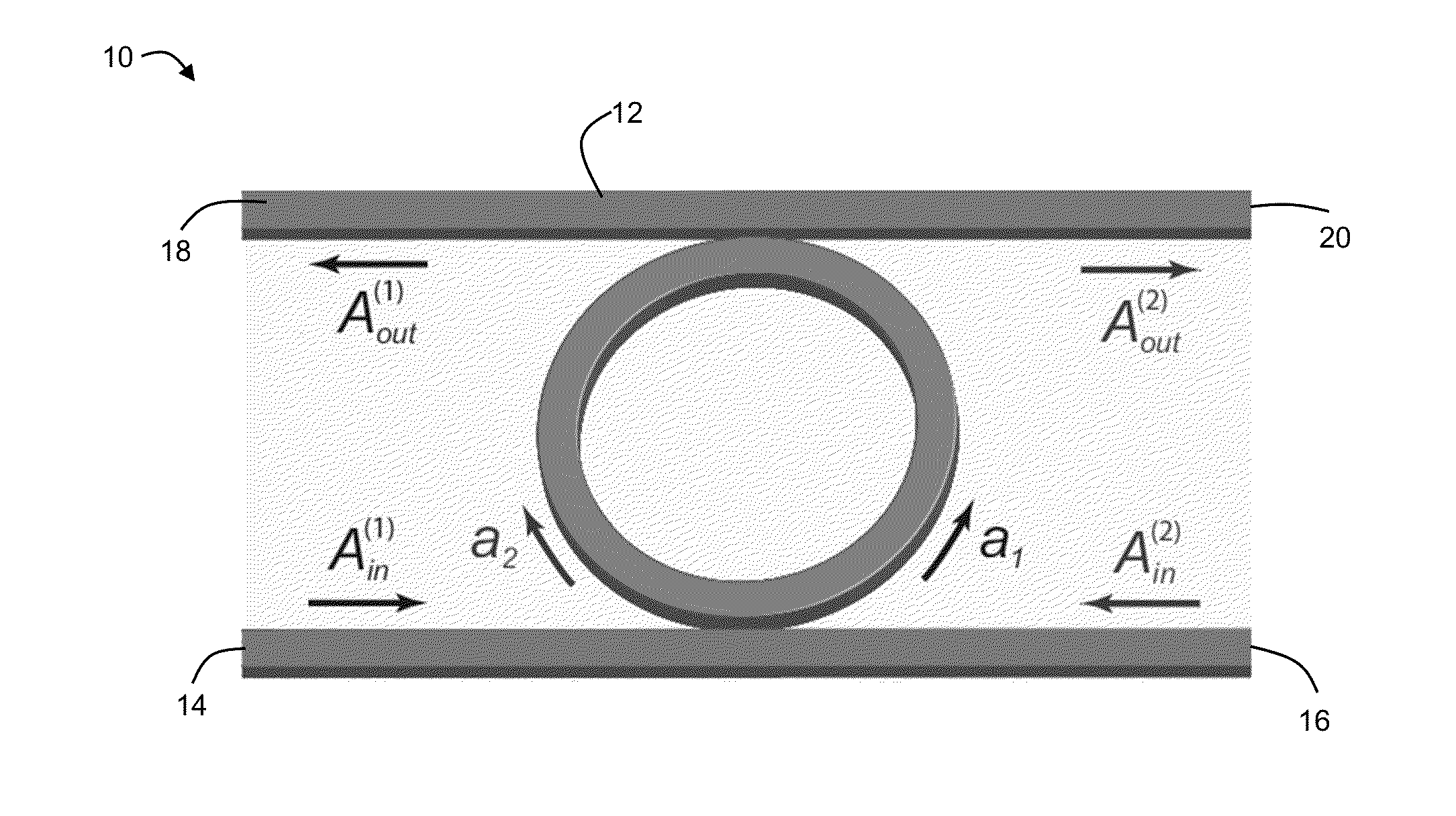
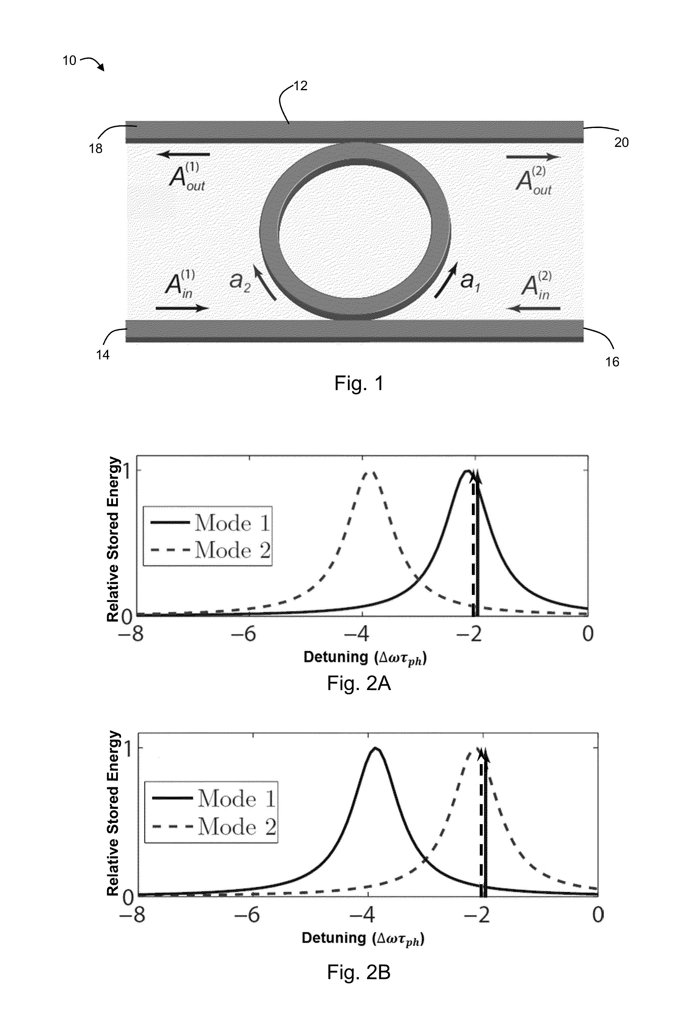
[0020]The present invention may be embodied as an optical flip-flop 10, shown schematically in FIG. 1. In an embodiment, the flip-flop 10 comprises a micro-ring resonator 12 having two inputs 14, 16 and two outputs 18, 20. In this embodiment, two resonator modes (a1 and a2), excited by two input beams (Ain(1) and Ain(2)) near a specific resonance frequency ωr, propagate in the clockwise (a2) and counter-clockwise (a1) directions. It should be noted that the present description is an exemplary embodiment, and that the present invention and the results disclosed herein are applicable to any kind of dielectric resonator (such as, for example, photonic-crystal micro-cavities and whispering-gallery-mode resonators) so long as the two excited modes are distinguishable (e.g., by having different resonance frequencies, etc.) The physical origin of two-input bistability is the asymmetry between Kerr-induced self- and cross-phase modulations (“SPM” and “XPM,” respectively). For example, in th...


PUM

PropertyMeasurementUnit
phaseaaaaaaaaaa
photon lifetimeaaaaaaaaaa
phase shiftaaaaaaaaaa

Abstract

A two-input bistable resonator that can be switched in a robust way by phase modulation of the input beams is presented. An optical flip-flop of the present invention may be embodied as a two-input Kerr resonator. The disclosed switching mechanism is compatible with cross-phase modulation induced by set and reset pulses for realization of an ultrafast, passive, all-optical memory element.

Description

FIELD OF THE INVENTION[0001]The present disclosure relates to optical circuits, and more particularly to optical flip flop circuits.BACKGROUND OF THE INVENTION[0002]Optical flip-flops are the key elements of all-optical memory and buffering devices. The development of such devices remains in its infancy, even though flip-flops would be valuable in contemporary communication networks. The reason for this is that flip-flops are not yet fast, robust, and low-power enough to be used in the large numbers that these applications demand. The most common means of implementing optical flip-flops is the use of active semiconductor devices. Both semiconductor optical amplifiers and semiconductor lasers have been widely used for this purpose. An alternative would be to use the Kerr effect in a passive, bistable resonator. This second approach has two potential advantages. First, passive flip-flops do not require current injection and devices that require cascading of such elements could be impl...

Claims


Application Information

Patent Timeline
Patent Type & Authority Applications(United States)
IPC IPC(8): G02F3/02
CPCG02F3/026G02F1/3511G02F3/024
Inventor AGRAWAL, GOVINDDANIEL, BRIAN
Owner UNIVERSITY OF ROCHESTER
Why Eureka
Try Eureka