Centrifugal separator

a centrifugal separator and centrifugal technology, applied in centrifuges, crankcase ventilation, machines/engines, etc., can solve the problems of unreliable and inefficient separation, oil contamination of cleaned gas, etc., and achieve the effect of avoiding or reducing sticky agglomerations

Active Publication Date: 2015-04-30
ALFA LAVAL CORP AB
View PDF5 Cites 9 Cited by
  • Summary
  • Abstract
  • Description
  • Claims
  • Application Information

AI Technical Summary

Benefits of technology

[0007]The object of the present invention is to remedy or alleviate the problems discussed above, and to avoid or reduce sticky agglomerat

Problems solved by technology

If too much oil is supplied to the separation space, the oil will contaminate the cleaned gas.
Hence, too mu

Method used


Image

  • Centrifugal separator
  • Centrifugal separator
  • Centrifugal separator

Examples


first embodiment

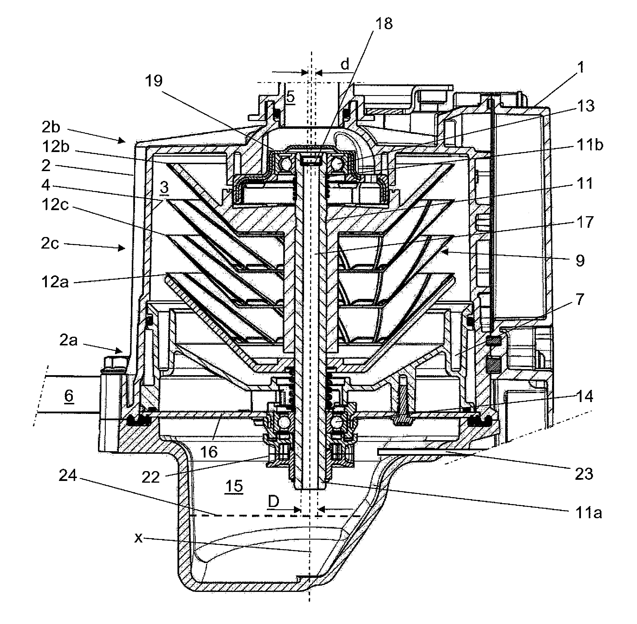
[0030]FIG. 1 discloses a centrifugal separator for cleaning a gas containing oil, such a crankcase gases from an internal combustion engine (not disclosed). FIG. 1 also discloses a pressure control valve 1 designed to keep the pressure within a safe range in the crankcase of the internal combustion engine.

[0031]The centrifugal separator comprises a stationary casing 2 defining a separation space 3 within the stationary casing 2. The stationary casing 2 is stationary in relation to the internal combustion engine 1. The stationary casing 2 comprises a first end portion 2a, an opposite second end portion 2b, and an intermediate portion 2c provided between and adjoining the first end portion 2a and the second end portion 2b. In the embodiments disclosed, the first end portion 2a forms a lower portion during operation of the centrifugal separator, whereas the second end portion 2b forms an upper portion.

[0032]The stationary casing 2 has an inner wall surface 4 facing the separation space...

third embodiment

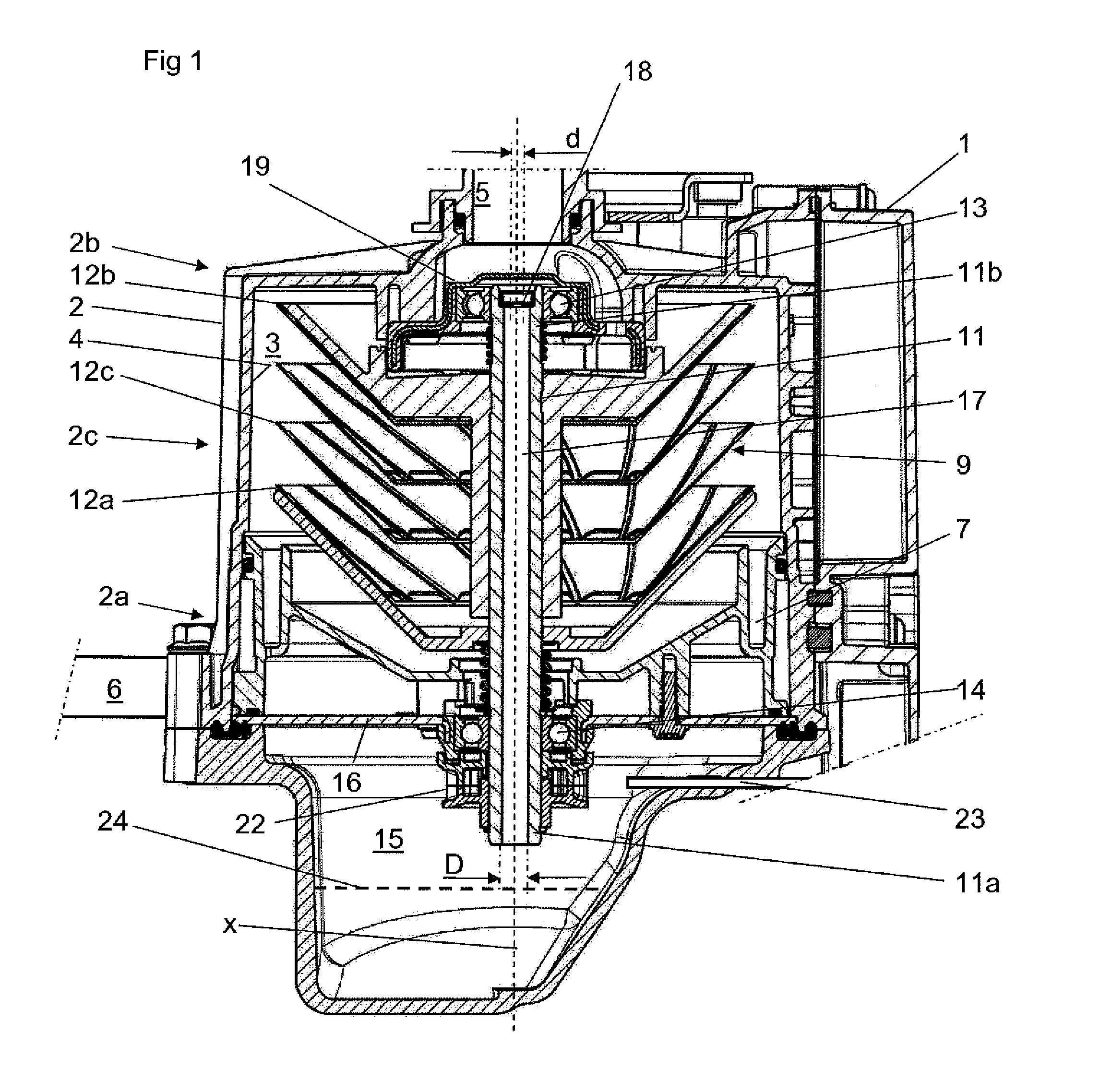
[0052]In the third embodiment, the aperture diameter of the inlet nozzle 18 is 0.3 to 1.5 mm, preferably, 0.4 to 1.0 mm, for instance 0.5 mm. The oil may then be supplied to the inlet nozzle 18 at a pressure of 3-6 bars.

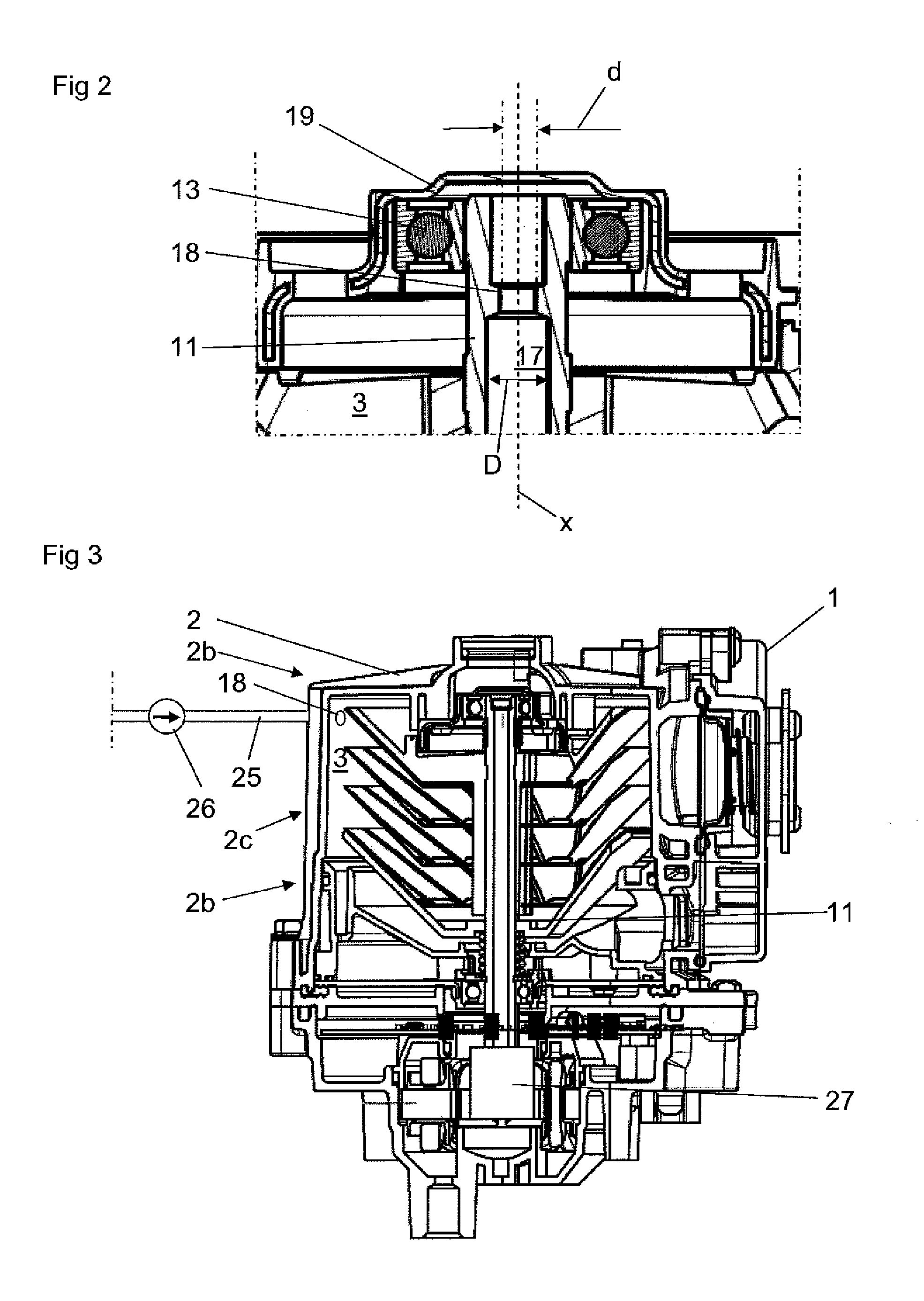
[0053]Furthermore, in the third embodiment, the drive member is replaced by and comprises a separate motor, e.g. an electrical motor 27, connected to the spindle 11 for rotating the spindle 11 and the centrifuge rotor 9. The separate motor may alternatively comprise a separate pneumatic motor or a separate hydraulic motor. The spindle 11 and the centrifuge rotor 9 may also be driven by means of the crankshaft of the internal combustion engine.


PUM


Abstract

A centrifugal separator for cleaning crankcase gas, containing oil, from an internal combustion engine, includes a stationary casing defining a separation space and including a first end portion, an opposite second end portion and an inner wall surface facing the separation space. The separator also includes an inlet channel for the gas to be cleaned, a gas outlet channel for the cleaned gas and an oil outlet for the separated the oil. A centrifuge rotor is provided in the separation space and includes a spindle and a plurality of separation discs carried by the spindle. The centrifuge rotor is rotated to create a rotating gas volume. An oil supply device supplies such a quantity of oil to the separation space that a flowing oil film is created on the inner wall surface during operation of the centrifugal separator.

Description

THE FIELD OF THE INVENTION[0001]The present invention refers to a centrifugal separator for cleaning a gas containing oil, especially for cleaning crankcase gases from an internal combustion engine, such as a diesel engine. More specifically, the present invention refers to a centrifugal separator according to the pre-characterizing portion of claim 1, see WO 2004 / 022239.BACKGROUND OF THE INVENTION AND PRIOR ART[0002]Crankcase gases from internal combustion engines contain oil in the form of an oil mist or oil droplets mixed with other impurities such as soot and hydrocarbons. Such impurities in the crankcase gases may form sticky substances. Furthermore, it is common to add various additives to the oil of the internal combustion engine in order to improve the properties of the oil for the lubrication and cooling of the internal combustion engine. However, such additives may have a negative effect due to the fact that the impurities, such as soot and hydrocarbons, form substances th...

Claims


Application Information

Patent Timeline
IPC IPC(8): F01M13/04B04B9/06B04B5/12
CPCF01M13/04B04B5/12B04B2005/125F01M2013/0422B04B9/06B04B11/02
Inventor POGEN, MATS-ORJAN
Owner ALFA LAVAL CORP AB
Why Eureka
Try Eureka